ECDSA256V-IP Reference Design
2.1 Test with Custom ECDSA Parameters
2.2 Test with NIST Test Vector
This document describes the details of ECDSA256V-IP reference design. In this reference design, ECDSA256V-IP is used to verify digital signatures signed with NIST P-256 curves. Users can verify a signature with input required parameters, test compliance with NIST test vectors and verify SSL certificate as real-life application. More details of the hardware design and CPU firmware are described as follows.
1 Hardware
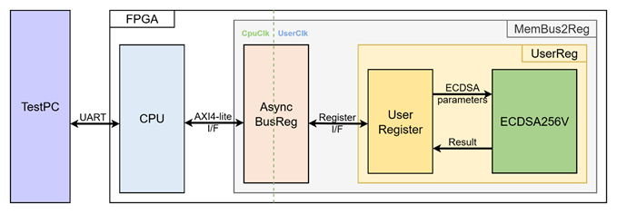
Figure 1 ECDSA256V-IP reference design block diagram
In this test environment, the CPU system is designed to interface with the user through a serial console on the test PC and with the FPGA logic through a memory-mapped bus (AXI4-Lite). The MemBus2Reg module translates the memory-mapped bus transactions into a simple register interface using AsyncBusReg.
Within the UserReg module, the ECDSA256V-IP connects to user register that provide the ECDSA parameters, control signals and status/result output for the verification process, as shown in Figure 1.
Since the CPU system and the ECDSA256V-IP operate in different clock domains, the AsyncBusReg module inside MemBus2Reg is implemented as an asynchronous circuit to support clock domain crossing.
The details of each hardware module are described in the following sections.
1.1 MemBus2Reg Module
The MemBus2Reg module interfaces with the CPU through a memory-mapped bus, such as AXI4-Lite. The hardware registers within MemBus2Reg are mapped to specific CPU memory addresses, as shown in Table 1. These registers include control and status registers that enable the CPU to access and manage the module.
MemBus2Reg consists of two main sub-modules: AsyncBusReg and UserReg. The AsyncBusReg sub-module is responsible for converting the signals from the memory-mapped bus into a simple register interface that uses a 32-bit data bus, maintaining consistency with the bus’s data size. As shown in Figure 1, the MemBus2Reg module operates with two clock domains: CpuClk, which interfaces with the CPU, and UserClk, which operates in the user-defined clock domain. The AsyncBusReg sub-module includes circuitry to handle asynchronous communication between these two clock domains.
1.2 AsyncBusReg
This module is designed to convert the signal interface of a memory-mapped bus into a register interface. Also, it enables two clock domains, CpuClk and UserClk domain, to communicate.
To write register, RegWrEn is asserted to ‘1’ with the valid signal of RegAddr (Register address in 32-bit unit), RegWrData (write data of the register), and RegWrByteEn (the byte enable of this access: bit[0] is write enable for RegWrData[7:0], bit[1] is used for RegWrData[15:8], …, and bit[3] is used for RegWrData[31:24]).
To read register, AsyncBusReg asserts RegRdReq=‘1’ with the valid value of RegAddr (the register address in 32-bit unit). After that, the module waits until RegRdValid is asserted to ‘1’ to get the read data through RegRdData signal at the same clock as shown in Figure 2.

Figure 2 Register interface timing diagram
1.3 UserReg
Table 1 Register map Definition
|
Address offset |
Register Name |
Rd/Wr |
Description |
|
0x0000 |
ECDSA_VERSION_REG |
Rd |
[31:0] – ECDSA256V-IP version (wVersion). |
|
0x0004 |
ECDSA_RESETB_REG |
Rd |
[0] – Active low reset signal for ECDSA256V-IP (rECDSARstB). |
|
0x0010 |
ECDSA_START_REG |
Rd |
[0] – Busy status of ECDSA256V-IP (rBusy) |
|
Wr |
[0] – Start signal for ECDSA256V-IP (rStart) |
||
|
0x0014 |
ECDSA_RESULT_REG |
Rd |
[0] – Verification result (rResult). |
|
0x0020- |
ECDSA_Qx_0_REG- |
Rd/Wr |
[31:0] – Public key x-coordinate (little-endian) (rQx). |
|
0x0040- |
ECDSA_Qy_0_REG- |
Rd/Wr |
[31:0] – Public key y-coordinate (little-endian) (rQy) |
|
0x0060- |
ECDSA_R_0_REG- |
Rd/Wr |
[31:0] – r component of signature (little-endian) (rR) |
|
0x0080- |
ECDSA_S_0_REG- |
Rd/Wr |
[31:0] – s component of signature (little-endian) (rS) |
|
0x00A0- |
ECDSA_HASH_0_REG- |
Rd/Wr |
[31:0] – Message digest (little-endian) (rHash) |
For ECDSA parameter configuration, the x-coordinate of the public key is written to the registers ECDSA_Qx_7_REG through ECDSA_Qx_0_REG. The same procedure applies to the y-coordinate of the public key, the signature components r and s, and the message digest, as illustrated in Figure 3.
To start the verification process, the CPU writes to ECDSA_START_REG, which asserts rStart for one clock cycle. The ECDSA_START_REG can also be read to monitor the rBusy status. Once wBusy is de-asserted, the verification result can be obtained by reading ECDSA_RESULT_REG as illustrated in Figure 4.
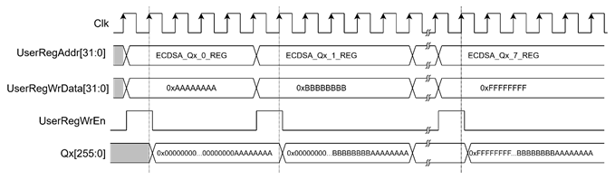
Figure 3 Timing diagram of ECDSA parameter configuration
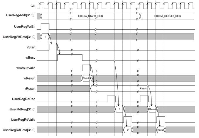
Figure 4 Timing diagram of verification process
2 CPU Firmware
After system boot-up, CPU initializes its peripherals such as UART and Timer a shows IP version of ECDSA256V-IP. Then main menu is displayed. Main function runs in an infinite loop to show the main menu and get keyboard input from user. User can select each menu via serial console that will call the related functions. After functions finished running, the main menu is displayed again. More details of the sequence in each menu are described as follows.
2.1 Test with Custom ECDSA Parameters
This menu is used to verify an ECDSA signature by entering user-provided ECDSA parameters. Five parameters are required in this mode: x- and y-coordinates of the public key (Qx, Qy), the signature components (r, s), and the message digest (hash). Each parameter is set individually using the set_256bit_register function, as described in Table 2. After all parameters are configured, the ecdsa_verify function is called to initiate the ECDSA256V-IP, monitor its status, and report the verification result through the serial console. The detail of ecdsa_verify() function is provided in Table 3.
Table 2 set_256bit_register function
|
void set_256bit_register(unsigned int *start_addr, char *label) |
|
|
Parameter |
start_addr: Pointer to the register address where the parameter will be written. label: Name of the signal associated with the parameter. |
|
Return value |
None |
|
Description |
This function displays the current parameter value on the console and prompts the user for input. A new parameter can be entered in hexadecimal format, or the user may press ENTER to skip and keep the existing value. If the input is not in hexadecimal format, it will be ignored. Once valid input is received, the function waits until the busy status is cleared, and then writes the new value to the specified registers. |
Table 3 ecdsa_verify function
|
int ecdsa_verify(void) |
|
|
Parameter |
None |
|
Return value |
1: Signature is valid. 0: Signature is invalid -1: Error occurred |
|
Description |
This function initiates the ECDSA256V-IP to verify a signature using the currently set parameters. It continuously monitors the busy status until the operation completes. If a timeout occurs during the process, the function returns -1. Otherwise, it returns the verification result (1 for valid or 0 for invalid). |
2.2 Test with NIST Test Vector
This function consists of four main steps:
1) Check RSP File Type – Reads file header comments and verifies whether the curve/hash group is supported.
2) Parse Test Cases – Extracts the ECDSA parameters and expected verification results from the RSP file. Since the messages within the NIST test vectors are not pre-hashed, the software hashes each message before storing it as a test case parameter.
3) Run Verification – Configures the ECDSA parameters for each test case, calls the ecdsa_verify() function, and compares the actual result with the expected outcome.
4) Display Summary – Presents the results in a test summary table.
2.3 Test with PEM Certificate
This menu is used to verify SSL certificates in PEM format. The process works as follows:
1) Receive certificate input – Calls the cert_read_pem_from_uart function to receive the certificate from the user via the serial console and extract individual certificates from the PEM format (see Table 4).
2) Parse each certificate – parses the certificate parameters and stores the result in CertParams structure.
3) Verify each certificate – If the certificate uses ECDSA-with-SHA256, the public key (in uncompressed format) and signature are extracted. The ECDSA parameters are then configured as inputs, and the ECDSA256V-IP is called to perform the verification. The result is recorded.
4) Display verification results – Outputs the verification results for each certificate directly onto the serial console.
Table 4 cert_read_pem_from_uart function
|
int cert_read_pem_from_uart(char * der_buf, int max_len, int *cert_starts, int max_certs) |
|
|
Parameter |
der_buf: pointer of the char array that stores the certificate chain max_len: maximum certificate length allowed cert_starts: byte offset in der_buf where cert i begins max_certs: maximum number of certificates allowed |
|
Return value |
The number of certificates decoded, or -1 on error/timeout with no data. |
|
Description |
This function receives the certificate from user via serial console. It terminates when a Cancel command (Ctrl+X) is detected. |
3 Revision History
|
Revision |
Date (D-M-Y) |
Description |
|
1.00 |
02-Jun-26 |
Initial version release |