100G Ethernet Data Logger Using NVMe-IP for Gen5
Demo Instruction
2 100G Ethernet Data Logger Demo
2.2.1 Display Packet Filter Setting
2.2.2 Display File System Information
1 Overview
This document provides instructions for operating the 100G Ethernet data logger using NVMe-IP (Gen5) demo on FPGA development boards. The system enables users to capture Ethernet traffic exchanged between two 100G Ethernet devices through the EMAC interfaces and record it to an NVMe SSD.
Captured packets are stored in PCAPNG file format, allowing the recorded traffic to be opened and analyzed using standard network analysis tools such as Wireshark.
During packet recording, the system uses internal DDR memory as a temporary packet buffer before writing data to the NVMe SSD. Packet filtering parameters are configured by the user through the test application (Packet Filtering Config), which runs on the host PC and communicates with the FPGA via the console interface, as illustrated in Figure 1.
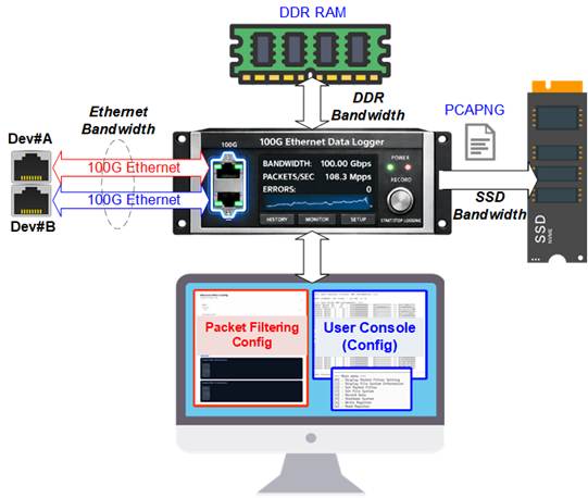
Figure 1 100G Ethernet Data Logger Usage
Ethernet traffic between Device #A and Device #B is exchanged without packet loss. However, the packet recording throughput is constrained by the hardware characteristics of the DDR memory subsystem and the NVMe SSD, rather than by the Ethernet interfaces themselves.
In the demo system, the maximum aggregate DDR bandwidth (combined write and read) is approximately 16.8 GB/s. Since packet recording requires simultaneous DDR read and write operations, the maximum sustainable recording throughput to the NVMe SSD is limited to 8.4 GB/s.
In addition, the NVMe Gen5 SSD must support a sustained write speed of at least 8.4 GB/s to fully utilize this capability. If the SSD write performance is lower, the maximum recording bandwidth will be limited by the SSD instead of the DDR subsystem.
The effective maximum recording bandwidth for Ethernet packets can be calculated using the following equation:
Max 100GbE BW = min (DDR bandwidth, NVMe bandwidth) x Ethernet packet size / (Ethernet packet size + 32)
where the additional 32 bytes
represent protocol overhead per packet.
For a system where DDR supports simultaneous read/write at 8.4 GB/s, and the NVMe Gen5 SSD supports sustained write performance exceeding 8.4 GB/s, the maximum achievable recording bandwidth depends on the Ethernet packet size, as summarized in Table 1.
Table 1 Maximum Bandwidth of 100G Ethernet Packet Recording
|
Ethernet Packet Size (Bytes) |
Maximum Bandwidth (MB/s) |
|
60 |
5,478 |
|
64 |
5,600 |
|
72 |
5,815 |
|
96 |
6,300 |
|
128 |
6,720 |
|
160 |
7,000 |
|
192 |
7,200 |
|
512 |
7,906 |
|
1024 |
8,145 |
|
1460 |
8,220 |
|
4096 |
8,335 |
|
8192 |
8,367 |
|
9014 |
8,370 |
As packet size increases, the impact of per-packet overhead is reduced, allowing the recording bandwidth to approach the maximum limit of 8.4 GB/s.
This guide describes how to configure parameters and run the demo via the FPGA console. It also explains the test procedure and provides example results.
2 100G Ethernet Data Logger Demo
Before executing the demo, ensure that the hardware and software environments are fully prepared according to the FPGA setup guide “NVMeIPG5-100gbe-datalogger-fpgasetup”.
The demo includes a Packet Filtering Configuration application, which uses two independent packet filter parameter sets:
· Packet Filter#0: Filters and records packets transmitted from Ethernet #0 to Ethernet #1
· Packet Filter#1: Filters and records packets transmitted from Ethernet #1 to Ethernet #0
Each packet filter supports up to eight configurable filtering rules, which are described in detail in Section 2.2.3.
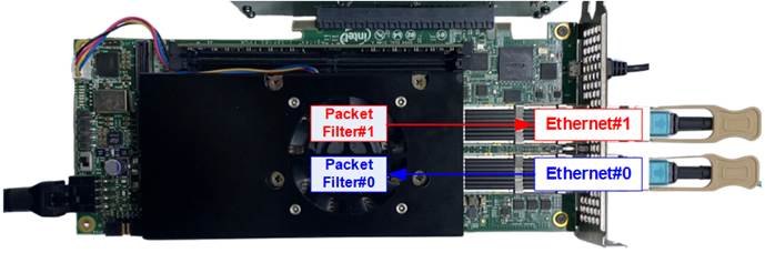
Figure 2 Ethernet and Packet Filtering Channels
This section describes the demo execution flow, which consists of two main phases: System Initialization to initialize all hardware components and verifies system readiness, and Data Logging Operation to configure packet filtering and records Ethernet traffic to the NVMe SSD.
Detailed procedures for each phase are provided in the following subsections.
2.1 System Initialization
After the configuration file is downloaded to the FPGA, a welcome message is displayed on the console, showing the demo name, IP name, and IP version. The system then performs a sequence of initialization steps to prepare the hardware and software for operation.
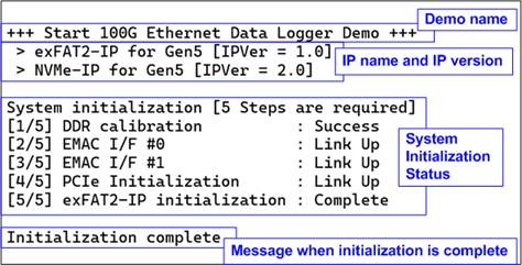
Figure 3 100G Ethernet Data Logger Initialization Message
As shown in Figure 3, the console displays the following initialization steps in order:
1) DDR calibration
2) EMAC interface#0 initialization
3) EMAC interface#1 initialization
4) PCIe initialization
5) exFAT2-IP initialization
Each step must complete successfully before the system
proceeds to the next one. When all steps are completed, the console displays
the message “Initialization complete”.
After initialization, the system automatically checks whether the connected SSD is formatted with Design Gateway’s exFAT-IP using a supported file size.
· If a supported exFAT file system is detected, the system displays the disk information on the console, as shown on the left side of Figure 4, and proceeds to the next step.
· If the SSD is not formatted with a supported exFAT file system, the system displays a warning message and prompts the user to perform either a Format or Secure Format operation, as shown on the right side of Figure 4.
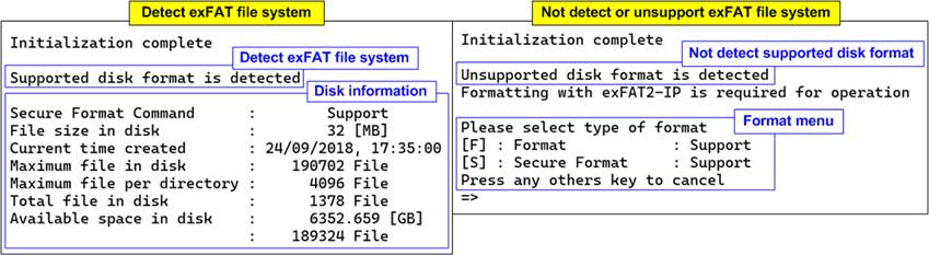
Figure 4 Connected SSD with and without exFAT File System Using Supported File Size
If the SSD is not formatted with DG’s exFAT-IP using a supported file system, executing either Format or Secure Format is mandatory before continuing.
· If the user performs Format or Secure Format: After the formatting process completes successfully, the system displays the disk information, including file size, maximum number of files supported, maximum number of files per directory, total number of existing files, and available disk space. The system then proceeds to the next step of the demo, as shown on the left side of Figure 5.
· If the user skips Format or Secure Format: As shown on the right side of Figure 5, the system prompts the user to select the Shutdown option.
- If the user declines shutdown, the system returns to the prompt to execute Format or Secure Format.
- The user must explicitly select either (Secure) Format or Shutdown before proceeding.
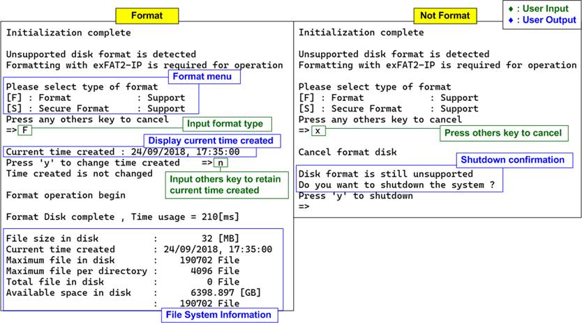
Figure 5 Initialization with and
without Format Operation
Once the SSD file system is validated or successfully formatted, the system proceeds to packet filter configuration.
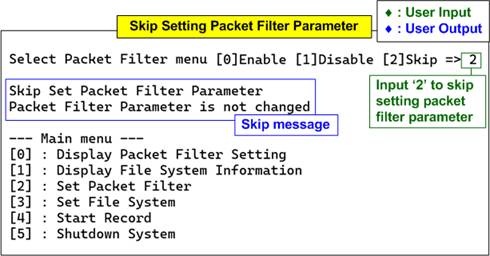
Figure 6 Packet Filter Parameters and Main Menu
The console displays the current packet filter parameter settings and waits for user input to select the desired filter options. Detailed instructions for configuring packet filter parameters are provided in Section 2.2.3.
After the packet filter configuration is completed, the main menu is displayed. Further details of each test menu are described in the next section.
2.2 Data Logger Main Menu
2.2.1 Display Packet Filter Setting
Select ‘0’ from the main menu to display the current packet filter settings. The console shows the configuration of packet filter parameters for both Channel #0 and Channel #1, as illustrated in Figure 7.
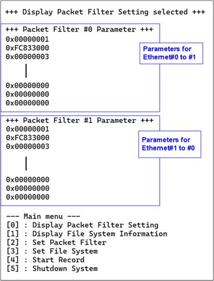
Figure 7 Display Packet Filter Configurations
The values displayed on the console correspond to the settings configured using the Packet Filtering Config application. These settings include:
· Control flags to enable or disable each filtering rule
· Control flags to enable or disable header byte verification
· Match values used to compare against each packet header byte for each rule
Detailed descriptions of all packet filter parameters are provided in the source code of the Packet Filtering Config application and the corresponding CPU firmware.
2.2.2 Display File System Information
Select ‘1’ from the main menu to display the current SSD file system information. The console shows the file system size, file creation time, maximum number of files supported, current number of files, and available disk space, as illustrated in Figure 8.
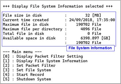
Figure 8 Display File System Information
2.2.3 Set Packet Filter
Select ‘2’ from the main menu to configure the packet filter parameters.
To enable the packet filtering feature, select submenu ‘0’. When packet filtering is enabled, a set of input parameters is required. These parameters can be copied directly from the console output generated by the Packet Filtering Config application.
If other submenus are selected, packet filter configuration is not required.
Note: In the evaluation version, packet filtering must be enabled for all eight rules: two rules for TCP, two rules for UDP, two rules for ARP, and two rules for ICMP.
In addition, each protocol has specific input constraints in the evaluation version. These constraints are removed when using the full version.
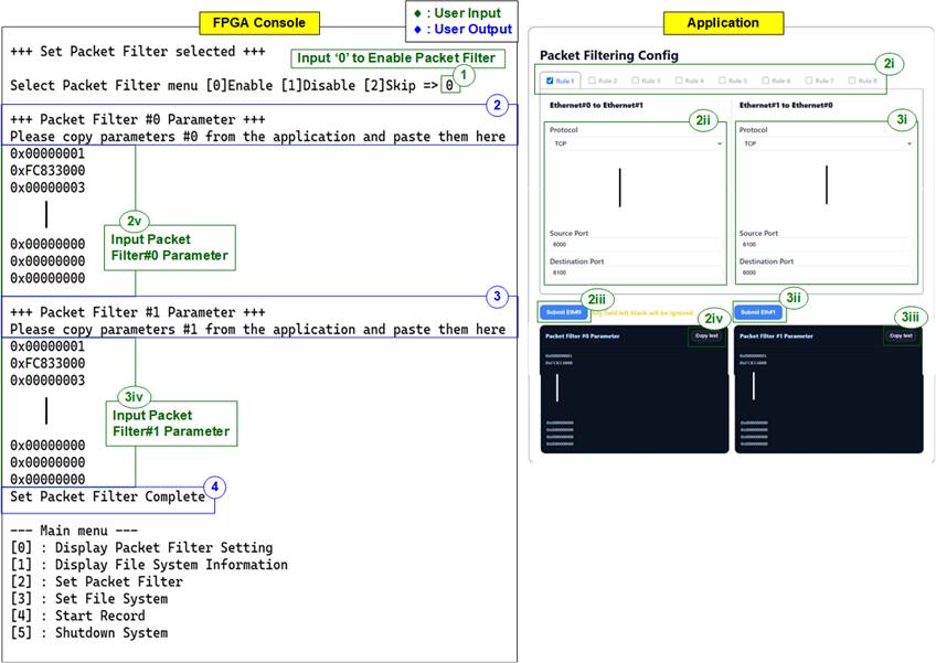
Figure 9 Set Packet Filter
To configure the packet filter parameters, follow these steps:
1) Select menu [0] to enable the packet filtering function.
2) The console displays a prompt requesting configuration parameters for Packet Filter#0.
i) Enable Rule #1 through Rule #8 by checking the corresponding boxes.
ii) For each enabled rule, configure the parameters for packets transmitted from Ethernet #0 to Ethernet #1.
Under each rule, select the protocol and specify its parameters. Any parameter may be left blank to indicate that all values are accepted for that field.
iii) Click “Submit Eth#0” to confirm the Ethernet #0 to Ethernet #1 parameters for all enabled rules. The application then displays the generated parameter set in the “Packet Filter #0 Parameter” box.
iv) Click “Copy text” to copy the parameter set for Ethernet #0 from the application.
v) Paste the copied parameter set into the FPGA console to complete the Packet Filter #0 configuration.
3) After completing Packet Filter #0, the console prompts the user to enter parameters for Packet Filter #1. The application automatically displays recommended values based on the Packet Filter #0 configuration, using the same protocols but with source and destination fields swapped.
The user may accept the recommended values or modify the parameters for Ethernet #1 individually for each enabled rule by repeating steps 2(ii)–2(v), applying them to the Ethernet #1 channel.
4) Once both packet filters are configured, the console displays the message “Set Packet Filter Complete” and returns to the main menu.
2.2.4 Set File System
Select ‘3’ from the main menu to initiate the exFAT2-IP formatting process. The console presents two formatting options: Format and Secure Format, and indicates whether the connected disk supports each command.
· Format: Performs standard file system formatting.
· Secure Format: Performs formatting with an additional erase operation to ensure that deleted data is irrecoverable. This option addresses data security requirements. On some SSDs, this operation may also improve data transfer performance that can degrade after extensive usage.
The execution steps for both Format and Secure Format are described below.
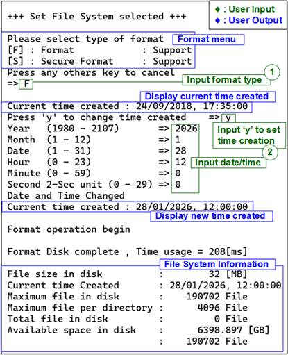
Figure 10 Set File System
· Press ‘F’ to execute Format.
· Press ‘S’ to execute Secure Format.
· Press any other key to cancel the operation. This action exits the (Secure) Format submenu and returns to the main menu.
If a Format option is selected, the system displays the default created date and time used for empty directories created during the formatting process.
2) Set Created Date and Time
· Press ‘y’ to modify the created date and time for new files, or press any other key to retain the default values. If modification is selected, enter the following parameters:
- Year : Range 1980 – 2107.
- Month : Range 1 – 12.
- Date : Range 1 – 31.
- Hour : Range 0 – 23.
- Minute : Range 0 – 59.
- Second : Value in 2-second steps (0, 2, …, 58); valid range 0 – 29 (representing 0 – 58 seconds).
All values are entered in decimal format by default. To enter hexadecimal values, prefix the value with “0x”. Invalid inputs are ignored, and the previous value is retained. After a successful update, the updated created date and time are displayed on the console.
· Press any other key (e.g., ‘n’) to retain the default date and time.
After the date and time configuration is completed, the Format or Secure Format operation begins automatically. During the operation, the console displays the message “Format operation begin”, and progress is indicated by dots (.).
Upon completion, the console displays “Format Disk complete”, along with the total formatting duration and file system information.
Note: The Secure Format operation typically takes longer than the standard Format operation due to the additional erase process.
2.2.5 Record Data
Select option ‘4’ from the main menu to start the data recording operation. After selection, the system checks whether the SSD has available space for recording. If the SSD is full, the system notifies the user and recommends selecting menu option [3] Set File System to format the SSD before continuing, as shown in Figure 11.
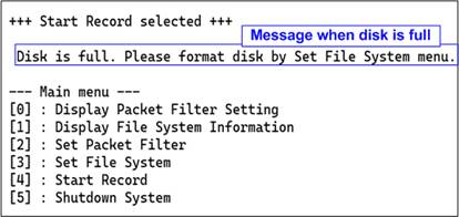
Figure 11 Message Due to Disk Full Status
If sufficient space is available, the system proceeds with the data recording operation.
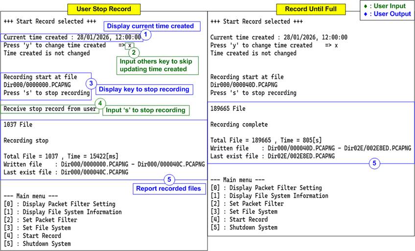
Figure 12 Record Data Result
Figure 12 illustrates the recording process in detail. The execution flow is as follows:
1) After the Start Record menu is selected, the console displays the current created date and time and prompts the user to change it.
2) Press ‘y’ to modify the created date and time, following the same procedure described in Section 2.2.4, step (2), or press any other key to retain the current value.
3) The console displays the first file name for the recording session. This file name corresponds to the next available file number following the latest existing file on the SSD. Before recording begins, the console displays the message “Press ‘s’ to stop recording”.
4) During recording, the console continuously displays the total number of recorded files on the SSD, allowing the user to monitor progress.
· Press ‘s’ to manually stop the recording.
· If no user action is taken, recording stops automatically when the SSD reaches its maximum storage capacity.
5) Once the recording operation stops, the console displays a summary including the total number of recorded files, total recording time, information on written data, and the last recorded file name.
The captured data is stored on the SSD in PCAPNG file format. File names range from the first recorded file number (the next available file after the latest existing file on the SSD) to the last recorded file number (the highest file index used during the session). Each file name consists of seven hexadecimal digits.
Due to directory file count limitations, recorded files may be distributed across multiple directories. The console displays the file names and their corresponding directory paths as the final message.
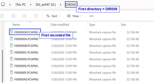
Figure 13 Example Test File Written by Record Data Operation
When the SSD is connected to a PC, the system recognizes the recorded files under the DG_exFAT drive subdirectories. The first file, F0000000.PCAPNG, is located in DIR000. The modified date of each file matches the created date and time configured during the Set File System operation.
Note: Do not create, write, or modify data on the SSD while it is connected to a PC. Any modification requires the SSD to be reformatted using exFAT2-IP to maintain file system integrity.
The PCAPNG files stored on the SSD can be opened and analyzed using standard network analysis tools such as Wireshark. An example of Ethernet packets captured in PCAPNG format is shown in Figure 14.
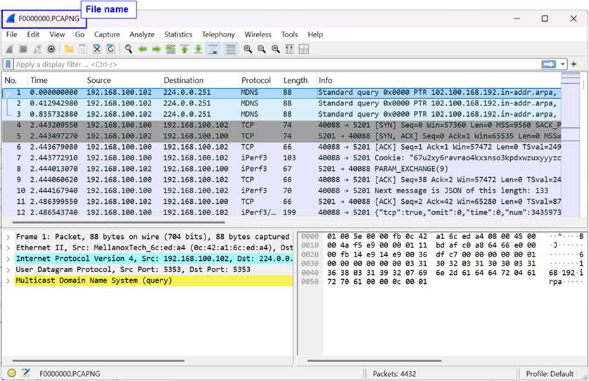
Figure 14 Recorded Data and Original Data
2.2.6 Shutdown System
Select option ‘5’ to initiate the Shutdown command. This command forces the system and the connected SSD to become inactive.
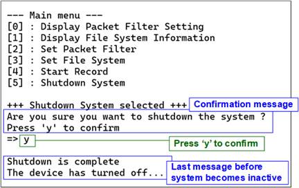
Figure 15 Shutdown System with Confirmation
When initiating the Shutdown operation, a confirmation message will appear on the console. To proceed with the shutdown, the user inputs ‘y’ or ‘Y’. Any other key will cancel the operation. After the command executes successfully, the console will display the message “Shutdown is complete”, indicating the system has been properly shut down.
3 Revision History
|
Revision |
Date (D-M-Y) |
Description |
|
1.00 |
9-Feb-26 |
Initial version release |