2.3.3 Hash with Message from User
2.3.4 Hash with Predefined Constant Patterns
3.2 Hash with Predefined Constant Patterns
1 Introduction
This document provides the details of the SHA2-IP reference design. In this design, the SHA2-IP is used to compute secure hash values from user-provided messages or predefined constant patterns. Users can configure the SHA2 variant and input messages through a serial console connected to the test PC. More details of the hardware design and CPU firmware are described as follows.
2 Hardware Overview
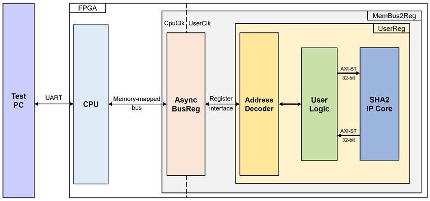
Figure 1 SHA2-IP reference design block diagram
As shown in Figure 1, UserReg is implemented inside the MemBus2Reg module. The CPU system communicates with the FPGA logic through memory-mapped bus (Avalon-MM) and interface with user through serial console in test PC.
Because CPU system and SHA2-IP operate in different clock domains, the AsyncBusReg block inside MemBus2Reg is designed as an asynchronous circuit to support clock-crossing operation. Also, AsyncBusReg converts memory-mapped bus signal which is standard bus in CPU system to be register interface. The details of MemBus2Reg module are described as follows.
2.1 MemBus2Reg Module
The MemBus2Reg module interfaces with the CPU through a memory-mapped bus, such as Avalon-MM. The hardware registers within MemBus2Reg are mapped to specific CPU memory addresses, as shown in Table 1. These registers include control and status registers that enable the CPU to access and manage the module.
MemBus2Reg consists of two main sub-modules: AsyncBusReg and UserReg. The AsyncBusReg sub-module is responsible for converting the signals from the memory-mapped bus into a simple register interface that uses a 32-bit data bus, maintaining consistency with the bus’s data size. As shown in Figure 1, the MemBus2Reg module operates with two clock domains: CpuClk, which interfaces with the CPU, and UserClk, which operates in the user-defined clock domain. The AsyncBusReg sub-module includes circuitry to handle asynchronous communication between these two clock domains.
2.2 AsyncBusReg
This module is designed to convert the signal interface of a memory-mapped bus into a register interface. Also, it enables two clock domains, CpuClk and UserClk domain, to communicate.
To write register, RegWrEn is asserted to ‘1’ with the valid signal of RegAddr (Register address in 32-bit unit), RegWrData (write data of the register), and RegWrByteEn (the byte enable of this access: bit[0] is used for RegWrData[7:0], bit[1] is used for RegWrData[15:8], …, and bit[3] is used for RegWrData[31:24]).
To read register, AsyncBusReg asserts RegRdReq=‘1’ with the valid value of RegAddr (the register address in 32-bit unit). After that, the module waits until RegRdValid is asserted to ‘1’ to get the read data through RegRdData signal at the same clock.
2.3 UserReg
For register file, UserReg is designed to write/read registers, control and check status of the SHA2-IP corresponding with write register access or read register request from AsyncBusReg module. Memory map inside UserReg module is shown in Table 1. Timing diagram of register interface is shown in Figure 2.
Table 1 Register map Definition of SHA2-IP
|
Address |
Register Name |
Rd/Wr |
Description |
|
SHA2 Control register |
|||
|
0x0000 |
SHA2_VERSION_REG |
Rd |
[31:0]: SHA2-IP Version (IPVersion). |
|
0x0010 |
USER_DATALEN_0_REG |
Wr/Rd |
[31:0]: Lower 32-bit of input length (rSHAInLength0). |
|
0x0014 |
USER_DATALEN_1_REG |
Wr/Rd |
[31:0]: Second 32-bit of input length (rSHAInLength1). |
|
0x0018 |
USER_DATALEN_2_REG |
Wr/Rd |
[31:0]: Third 32-bit of input length (rSHAInLength2). |
|
0x001C |
USER_DATALEN_3_REG |
Wr/Rd |
[31:0]: Upper 32-bit of input length (rSHAInLength3). |
|
0x0020 |
USER_SHA_CMD_REG |
Wr/Rd |
[2:0]: SHA2 algorithm selection (rSHAInCMD). |
|
0x0024 |
USER_SHA_READY_REG |
Rd |
[0]: SHA2-IP ready flag. (SHAInReady). |
|
0x0028 |
USER_SHA_DATAIN_REG |
Wr |
[31:0]: Input message data word (rSHAInData). |
|
Hash Stream Output |
|||
|
0x0030 |
USER_HASH_STM_0_REG |
Rd |
[31:0]: Streamed hash output (rHashOutStm[31:0]). |
|
0x0034 |
USER_HASH_STM_1_REG |
Rd |
[31:0]: Streamed hash output (rHashOutStm[63:32]). |
|
0x0038 |
USER_HASH_STM_2_REG |
Rd |
[31:0]: Streamed hash output (rHashOutStm[95:64]). |
|
0x003C |
USER_HASH_STM_3_REG |
Rd |
[31:0]: Streamed hash output (rHashOutStm[127:96]). |
|
0x0040 |
USER_HASH_STM_4_REG |
Rd |
[31:0]: Streamed hash output (rHashOutStm[159:128]). |
|
0x0044 |
USER_HASH_STM_5_REG |
Rd |
[31:0]: Streamed hash output (rHashOutStm[191:160]). |
|
0x0048 |
USER_HASH_STM_6_REG |
Rd |
[31:0]: Streamed hash output (rHashOutStm[223:192]). |
|
0x004C |
USER_HASH_STM_7_REG |
Rd |
[31:0]: Streamed hash output (rHashOutStm[255:224]). |
|
0x0050 |
USER_HASH_STM_8_REG |
Rd |
[31:0]: Streamed hash output (rHashOutStm[287:256]). |
|
0x0054 |
USER_HASH_STM_9_REG |
Rd |
[31:0]: Streamed hash output (rHashOutStm[319:288]). |
|
0x0058 |
USER_HASH_STM_10_REG |
Rd |
[31:0]: Streamed hash output (rHashOutStm[351:320]). |
|
0x005C |
USER_HASH_STM_11_REG |
Rd |
[31:0]: Streamed hash output (rHashOutStm[383:352]). |
|
0x0060 |
USER_HASH_STM_12_REG |
Rd |
[31:0]: Streamed hash output (rHashOutStm[415:384]). |
|
0x0064 |
USER_HASH_STM_13_REG |
Rd |
[31:0]: Streamed hash output (rHashOutStm[447:416]). |
|
0x0068 |
USER_HASH_STM_14_REG |
Rd |
[31:0]: Streamed hash output (rHashOutStm[479:448]). |
|
0x006C |
USER_HASH_STM_15_REG |
Rd |
[31:0]: Streamed hash output (rHashOutStm[511:480]). |
|
Address |
Register Name |
Rd/Wr |
Description |
|
Hash Latch Output |
|||
|
0x0070 |
USER_HASH_LATCH_0_REG |
Rd |
[31:0]: Latched hash output (rHashOutLatch[31:0]). |
|
0x0074 |
USER_HASH_LATCH_1_REG |
Rd |
[31:0]: Latched hash output (rHashOutLatch[63:32]). |
|
0x0078 |
USER_HASH_LATCH_2_REG |
Rd |
[31:0]: Latched hash output (rHashOutLatch[95:64]). |
|
0x007C |
USER_HASH_LATCH_3_REG |
Rd |
[31:0]: Latched hash output (rHashOutLatch[127:96]). |
|
0x0080 |
USER_HASH_LATCH_4_REG |
Rd |
[31:0]: Latched hash output (rHashOutLatch[159:128]). |
|
0x0084 |
USER_HASH_LATCH_5_REG |
Rd |
[31:0]: Latched hash output (rHashOutLatch[191:160]). |
|
0x0088 |
USER_HASH_LATCH_6_REG |
Rd |
[31:0]: Latched hash output (rHashOutLatch[223:192]). |
|
0x008C |
USER_HASH_LATCH_7_REG |
Rd |
[31:0]: Latched hash output (rHashOutLatch[255:224]). |
|
0x0090 |
USER_HASH_LATCH_8_REG |
Rd |
[31:0]: Latched hash output (rHashOutLatch[287:256]). |
|
0x0094 |
USER_HASH_LATCH_9_REG |
Rd |
[31:0]: Latched hash output (rHashOutLatch[319:288]). |
|
0x0098 |
USER_HASH_LATCH_10_REG |
Rd |
[31:0]: Latched hash output (rHashOutLatch[351:320]). |
|
0x009C |
USER_HASH_LATCH_11_REG |
Rd |
[31:0]: Latched hash output (rHashOutLatch[383:352]). |
|
0x00A0 |
USER_HASH_LATCH_12_REG |
Rd |
[31:0]: Latched hash output (rHashOutLatch[415:384]). |
|
0x00A4 |
USER_HASH_LATCH_13_REG |
Rd |
[31:0]: Latched hash output (rHashOutLatch[447:416]). |
|
0x00A8 |
USER_HASH_LATCH_14_REG |
Rd |
[31:0]: Latched hash output (rHashOutLatch[479:448]). |
|
0x00AC |
USER_HASH_LATCH_15_REG |
Rd |
[31:0]: Latched hash output (rHashOutLatch[511:480]). |
|
User Control register |
|||
|
0x00B0 |
USER_HASHVALID_REG |
Wr/Rd |
[0]: Status of Hash Stream is valid (rHashValid[0]). |
|
0x00B4 |
USER_HASHEMPTY_REG |
Wr |
[0]: Flag indicating if the input message size is empty (rSHAInEmpty). |
|
0x00B8 |
USER_TESTMODE_REG |
Wr |
[0]: Flag to enable hash with constant pattern (rSHAInConsWrEn). |
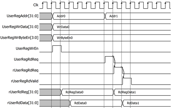
Figure 2 Register interface timing diagram
To read from a register, a multiplexer selects the read data based on UserRegAddr[7:2], which identifies the specific register. As shown in Figure 2, the read data becomes valid in the next two clock cycles. When UserRegRdReq is active, rUserRegRdReq is asserted to ‘1’, and rUserRdValid is activated with the valid read data corresponding to UserRegAddr. For writing to a register, UserRegWrEn is asserted to ‘1’ along with a valid UserRegAddr, indicating that the register is ready for writing.
In this reference design, there are five main operations related to configuration and data processing. Each operation is described as follows.
2.3.1 Length Setting
To set the length, the user configures a 128-bit length by writing to the registers USER_DATALEN_0_REG through USER_DATALEN_3_REG, which correspond to rSHAInlength0[31:0] through rSHAInlength3[31:0] as shown in Figure 3.
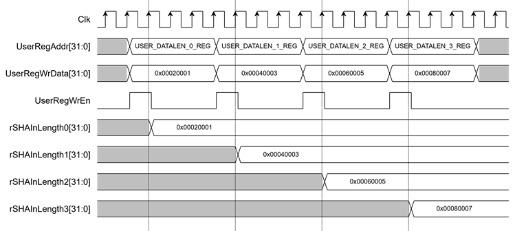
Figure 3 Timing diagram of Length setting process
2.3.2 Parameter Setting
For parameter setting, the user can configure the SHA2 algorithm by setting rSHAInCMD[2:0] through the USER_SHA_CMD_REG. If the user needs to hash an empty message, rSHAInEmpty must be set to ‘0’ by writing to the USER_HASHEMPTY_REG. Before starting the SHA2-IP, the rHashvalid[2:0] flags should be cleared to zero by writing to the USER_HASHVALID_REG, as shown in Figure 4.
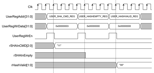
Figure 4 Timing diagram of parameter setting process
2.3.3 Hash with Message from User
To hash a message from the user, rSHAInMessageWrEn must be set to ‘1’ by writing the value 0x02 to USER_TESTMODE_REG. This configuration enables rSHAInValid to assert automatically when the user writes a message. As shown in Figure 5, when the user writes message to rSHAInData[31:0] via USER_SHA_DATAIN_REG, rSHAInValid will assert in the next clock cycle.
Before each write, the user must ensure SHAInReady=‘1’ by reading USER_SHA_READY_REG to confirm that SHA2-IP is ready to receive data. After rSHAInValid is asserted, rSHAInLength0 to rSHAInLength3 will decrement by the number of bytes written in the next clock cycle. For the final data word, rSHAInLast is asserted, and rSHAInKeep[3:0] is updated to reflect the number of remaining valid bytes.
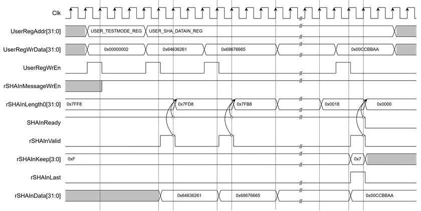
Figure 5 Timing diagram of Hash with Message from User process
2.3.4 Hash with Predefined Constant Patterns
To hash a predefined constant message, the user first writes the message to rSHAInData[31:0] via USER_SHA_DATAIN_REG. Then, to enable constant message hashing, rSHAInConsWrEn must be set to ‘1’ by writing 0x01 to USER_TESTMODE_REG. As shown in Figure 6, SHAInValid will assert when rSHAInConsWrEn is active.
Once rSHAInValid and SHAInReady are both asserted, rSHAInLength0 to rSHAInLength3 will decrement based on the number of bytes written in the next clock cycle. On the last word, rSHAInLast is asserted, and rSHAInKeep[3:0] is updated to indicate the remaining valid byte count.
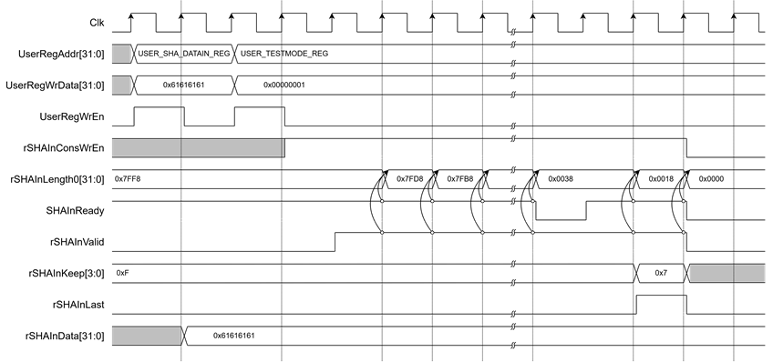
Figure 6 Timing diagram of Hash with Predefined Constant Patterns process
2.3.5 Hash Output
SHA2-IP supports two types of output: latched and streamed.
For latched output, the final hash value is stored in rHashOutLatch[511:0] when HashOutValid is asserted. The output format depends on the selected algorithm via rSHAInCMD[2:0]. When valid, rHashValid[1] is set to ‘1’. Users can read the latched hash result from USER_HASH_LATCH_0_REG to USER_HASH_LATCH_15_REG.
As shown in Figure 7, for example, when using SHA-256 (rSHAInCMD=“011”), the hash output is latched from HashOut256[255:0], and available through USER_HASH_LATCH_0_REG to USER_HASH_LATCH_7_REG.
For streamed output, the hash result is shifted into rHashOutStm[511:0]. When SHAOutValid is asserted, SHAOutData[31:0] is stored into the uppermost 32 bits (rHashOutStm[511:480]), and the rest shifts right by 32 bits. When both SHAOutValid and SHAOutLast are asserted, rHashValid[0] is set to ‘1’. Users can access the complete streamed hash via USER_HASH_STM_0_REG to USER_HASH_STM_15_REG.
As shown in Figure 8, for SHA-256 (rSHAInCMD=“011”), the streamed hash is constructed by sequentially writing SHAOutData[31:0] into rHashOutStm. The final hash can be read from USER_HASH_STM_7_REG to USER_HASH_STM_15_REG.
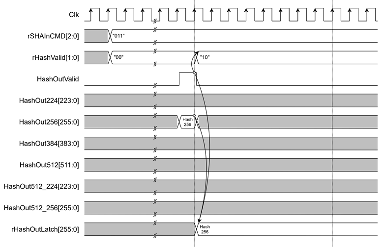
Figure 7 Timing diagram of Latched output Hash of SHA-256
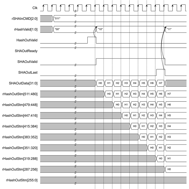
Figure 8 Timing diagram of Streamed output Hash of SHA-256
3 CPU Firmware
After system boot-up, CPU initializes its peripherals such as UART and Timer. Then the supported command usage is displayed. The main function runs in an infinite loop to show the main menu and get keyboard input from user. User can select each menu via serial console that will call the related functions. After functions finished running, the main menu is displayed again. More details of the sequence in each menu are described as follows.
3.1 Hash with Input Message
This menu is used to functionally test the SHA2-IP by generating a hash from a user-provided input message. The hash2message() function is called to initiate the process. The operational sequence is as follows:
1. Prompt the user to enter the input message
2. Set parameters in the SHA2-IP (input length, SHA variant), and start the timer
3. Write the input message to the SHA2-IP
4. Wait for the hashing process to complete, then stop the timer
5. Display the hash result from the latched output
6. Display the hash result from the streamed output
7. Display the execution time used for hashing
Table 2 hash2message function
|
void hash2message (unsigned int maxStr, unsigned int cmd) |
|
|
Parameter |
unsigned int maxStr: The maximum allowed length of the input string. unsigned int cmd: The SHA command type (e.g., CMD_SHA256). |
|
Return value |
None |
|
Description |
This function prompts the user to enter a message via UART, reads the message, calculates its SHA hash, displays the hash value, and shows the time taken for the operation. |
Table 3 getStr function
|
void getStr(char *str, unsigned int *strLen) |
|
|
Parameter |
char *str: Pointer to the string buffer where the input will be stored. unsigned int *strLen: Pointer to the length of the string. |
|
Return value |
None |
|
Description |
This function continuously reads characters from the UART until a newline is received. The string is stored in the provided `str` buffer and its length is updated in `strLen`. |
Table 4 wrStr function
|
void wrStr(char *str, unsigned int *strLen) |
|
|
Parameter |
char *str: Pointer to the string to be written. unsigned int *strLen: Pointer to the length of the string. |
|
Return value |
None |
|
Description |
This function writes the given string to the SHA input Data four characters at a time. It waits until the SHA is ready before writing each word. |
Table 5 show_hash function
|
void show_hash(unsigned int cmd) |
|
|
Parameter |
unsigned int cmd: The SHA command type determining hash length. |
|
Return value |
None |
|
Description |
This function reads the hash value from the latched output registers and prints the result in hexadecimal format to the UART console. |
Table 6 show_hash_stm function
|
void show_hash_stm(unsigned int cmd) |
|
|
Parameter |
unsigned int cmd: The SHA command type determining hash length. |
|
Return value |
None |
|
Description |
This function reads the hash value from the stream output registers and prints the result in hexadecimal format to the UART console. |
3.2 Hash with Predefined Constant Patterns
This menu is used to evaluate the computational efficiency of the SHA2-IP when processing large volumes of data. The hash2length() function is called to initiate the process. The operational sequence is as follows:
1. Prompt the user to enter the number of characters for the input message
2. Set parameters in the SHA2-IP (input length, SHA variant), and start the timer
3. Write a single 4-byte word containing the constant pattern to the SHA2-IP
4. After this initial write, the hardware logic automatically streams the constant pattern internally until the full input length is reached
5. Wait for the hashing process to complete, then stop the timer
6. Display the hash result from the latched output
7. Display the hash result from the streamed output
8. Display the execution time used for hashing
Table 7 show_hash_stm function
|
void hash2length(unsigned char consValue, unsigned int cmd) |
|
|
Parameter |
unsigned char consValue: The constant byte value (e.g., ‘a’) to stream as input data. unsigned int cmd: The SHA command (e.g., CMD_SHA256). |
|
Return value |
None |
|
Description |
This function prompts the user to enter a data length in bytes. It then sets the length in the register, configures the SHA core to process a stream of constant data, and starts processing. Finally, it displays the hash value and the time taken for the operation. |
3.3 SHA2 Variant Selection
SHA2-IP supports the following algorithm variants: SHA-224, SHA-256, SHA-384, SHA-512, SHA-512/224, and SHA-512/256. This menu allows the user to switch between these variants for hashing different messages based on desired output length. The default variant after system boot-up is SHA-512.
4 Revision History
|
Revision |
Date (D-M-Y) |
Description |
|
1.00 |
23-Apr-25 |
Initial version release |