2.3 Network properties setting
9 Test setup when using 2 FPGA boards
9.1 Environment setup when using 2 FPGA boards
9.2.1 Set parameters and start a server
9.2.2 Transmit data test (Server to client)
9.2.3 Receive data test (Client to server)
This document describes the instruction to demonstrate the operation of TLS1.3 Client 10Gbps IP Core (TLS10GC-IP) on ZCU106 Evaluation Board. In this demonstration, TLS10GC-IP is used to establish a secure connection using the Transport Layer Security protocol version 1.3 over TCP. This involves handling the TLS1.3 handshake, encrypting and decrypting data transferred between the user and server. Additionally, HTTPS is selected as the application layer protocol to simplify the testing of data transfer between a standard server and the TLS10GCdemo.
This instruction explains the process for users to use TLS10GCdemo as a client for uploading or downloading data patterns from the provided example node.js server, obtaining results similar to use a web browser. This instruction also covers the use of the “server” application to test transfer speed between a PC and TLS10GCdemo, as well as the comparison of test results between two FPGA boards.
1 Environment Setup
To operate TLS10GC-IP demo, please prepare following test environment.
1) FPGA development board: ZCU106 or KCU116 board.
2) Test PC with 10 Gigabit Ethernet or connecting with 10 Gigabit Ethernet card.
3) 10 Gb Ethernet cable:
a) 10 Gb SFP+ Passive Direct Attach Cable (DAC) which has 1-m or less length
b) 10 Gb SFP+ Active Optical Cable (AOC)
c) 2x10 Gb SFP+ transceiver (10G BASE-R) with optical cable (LC to LC, Multimode)
4) Micro USB cable for JTAG connection connecting between ZCU106 board and Test PC.
5) Micro USB cable for UART connection connecting between ZCU106 board and Test PC.
6) Vivado tool for programming FPGA installed on Test PC.
7) Serial console software such as TeraTerm installed on PC. The setting on the console is Baudrate=115200, Data=8-bit, Non-parity and Stop=1.
8) Demo configuration file (To download these files, please visit our web site at www.design-gateway.com)
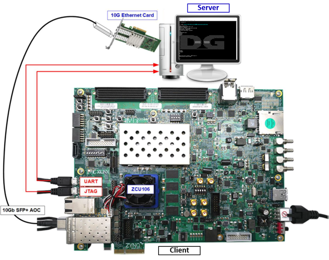
Figure 1 TLS10GCIP demo environment on ZCU106 board
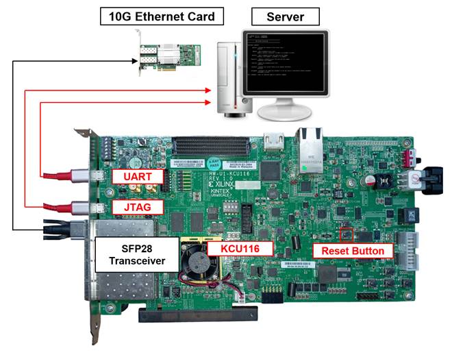
Figure 2 TLS10GCIP demo environment on KCU116 board
2 PC Setup
Before running demo, please check the network setting on PC. The example of setting 10 Gb Ethernet card is described as follows.
2.1 IP setting
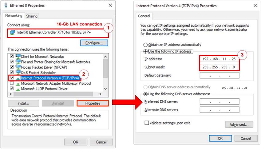
Figure 3 Setting IP address for PC
1) Open Local Area Connection Properties of 10 Gb connection, as shown in the left window of Figure 3.
2) Select “TCP/IPv4” and then click Properties.
3) Set IP address = 192.168.11.26 and Subnet mask = 255.255.255.0, as shown in the right window of Figure 3.
2.2 Speed and duplex setting
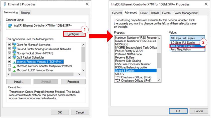
Figure 4 Set Link Speed = 10 Gbps
1) On Local Area Connection Properties window, click “Configure”, as shown in Figure 4.
2) On Advanced Tab, select “Speed and Duplex”. Set the value to “10 Gbps Full Duplex” for running 10 Gigabit transfer test, as shown in Figure 4.
2.3 Network properties setting
Some of network parameter setting may affect to network performance. The example of network properties setting as follows.
1) On “Interrupt Moderation” window, select “Disabled” to disable interrupt moderation which would minimize the latency during transferring data, as shown in Figure 5.
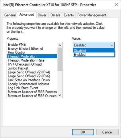
Figure 5 Interrupt Moderation
2) On “Interrupt Moderation Rate” window, set value to “OFF”, as shown in Figure 6.
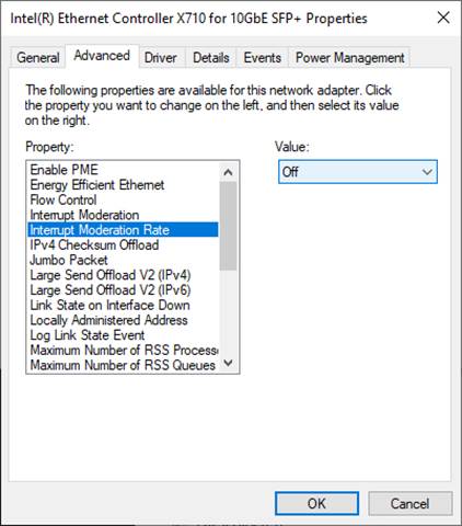
Figure 6 Interrupt Moderation Rate
3) On “Jumbo packet” window, set value to “9014 Bytes”, as shown in Figure 7.
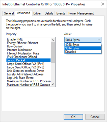
Figure 7 Jumbo packet
4) On “Receive Buffers” window, set value to the maximum value, as shown in Figure 8.
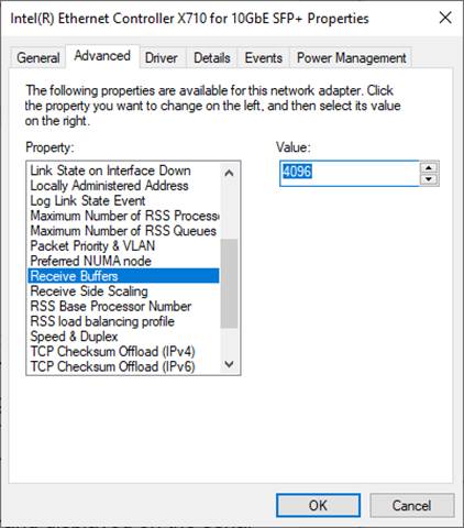
Figure 8 Receive Buffers
5) On “Transmit Buffers” window, set value to the maximum value, as shown in Figure 9.
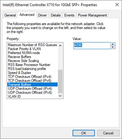
Figure 9 Transmit Buffers
3 Node.js server
In this demonstration, a sample server is created using Node.js. The server opens port 60001 for HTTPS connection. The required files for running the server are provided in server folder which contains the file as follow,
1) serverDemo.js for running server.
2) key.pem and cert.pem as a sample RSA key information and server’s certificate.
3) uploadMenu.html for making web browser can upload data to server via POST method.
4) server/log folder for containing files, DG.html, bike.html, pinkpanther.html and rex.html. Users can add files to server/log folder to be the resource for downloading.
When serverDemo.js is executed*, IP address and port number of server are displayed on console, as shown in Figure 10.
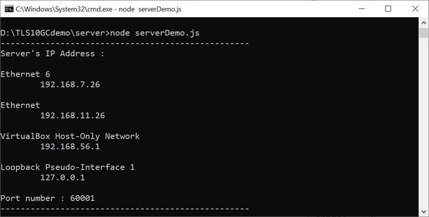
Figure 10 Server console when serverDemo.js is executed
Caution
When testing serverDemo.js with TLS10GCdemo, the FPGA board must be programmed before executing serverDemo.js to ensure that the server can detect the Ethernet interface between the FPGA board and the PC and can communicate properly.
By default, serverDemo.js does not verify data to optimize transfer speed. However, users can enable the data verification feature by including the “-v” parameter when executing serverDemo.js, as shown in Figure 11.
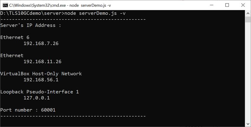
Figure 11 Server console when enabling verifying data
In case of client cannot access node.js server, please check firewall setting as below,
1) Go to Windows Defender Firewall with Advanced Security
2) Click on “Inbound Rules”
3) Search for “Node.js JavaScript Runtime” and open its properties
4) Go to “Protocols and Ports” tab and set Protocol type = TCP, Local port = Specific Ports that server on PC open. By default, the sample server opens port 60001. Local port number is set to 60001, as shown in Figure 12.
5) Go to “Advanced” tab and mark the profile boxes that match the network profile of ethernet card, as shown in Figure 13.
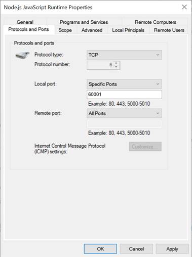
Figure 12 Protocols and Ports setting
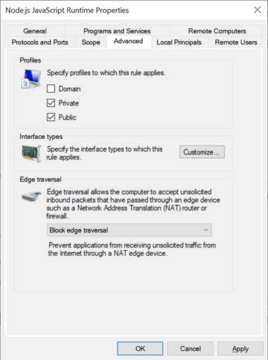
Figure 13 Advanced setting
Clients can download data patterns or existing files in the server/log folder by sending a GET command with URL.
For downloading data pattern, there are 4 data patterns which are increasing binary, decreasing binary, increasing text and decreasing text pattern. When a server receives a GET request, data pattern and length of requested data are displayed on the server console, as shown in Figure 14.
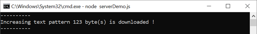
Figure 14 Server console when client download data pattern
For downloading html file in server/log folder, when a server receives a GET request, file path of requested data is displayed on the server console, as shown in Figure 15.
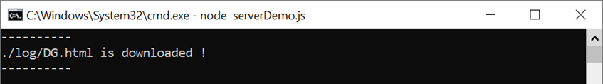
Figure 15 Server console when client download ./log/DG.html
Clients can upload data to the server by sending a POST command followed by uploaded data. After completely transferring, received data, length of data and transfer speed are displayed on the server console, as shown in Figure 16. If data length is more than 16 kB, the server console shows only data length and transfer speed.
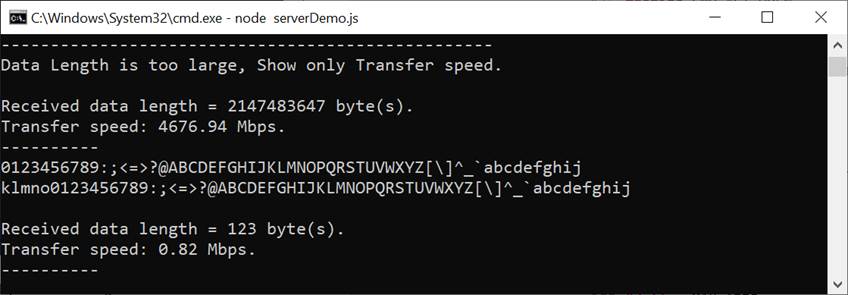
Figure 16 Server console when client upload data
4 Test software on PC
Due to the encrypting/decrypting process in the TLS protocol, Node.js server on the PC cannot achieve full-speed data transfer between PC and TLS10GC-IP. The “server” application is designed to run on the PC similar to the Node.js server for testing the performance of TLS10GC-IP via ethernet. The server opens port 60001 for HTTPS connection. Users can select the ethernet IP address for testing corresponding to the IP address of the 10 Gb Ethernet card, as shown in Figure 17.
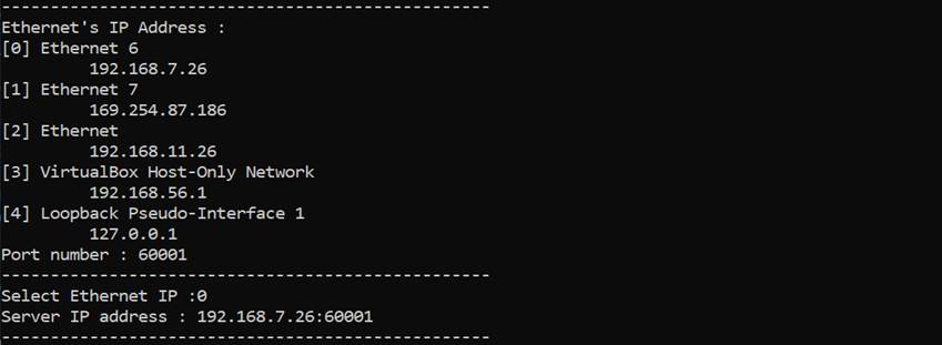
Figure 17 Server application console
For upload speed testing, after the handshake process is completed, “server” application will receive TxData from the client and count the number of received data to validate whether it matches the value form the URL. To achieve optimal data transfer speed, the received data will remain undecrypted and unverified. Then the transfer speed is displayed on the server console, as shown in Figure 18.
For download speed testing, after the handshake process is completed, “server” application will prepare the encrypted data pattern corresponding to the data pattern from the URL and continuously send it to the client. The download speed will be displayed on the server application console, as shown in Figure 19.
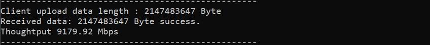
Figure 18 Server application console when testing upload speed
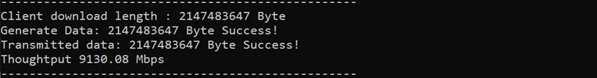
Figure 19 Server application console when testing download speed
5 Client web browser
Users can use a web browser for downloading data from server by GET method and uploading data to the server via POST method.
For downloading data pattern, user can input URL in the following format,
https://ip:port/direction/pattern/length
Where ip represent server’s IP address in dot-decimal notation
port represent server’s port number
direction represent download or upload
pattern represent data pattern
b1: increasing binary pattern, t1: increasing text pattern,
b0: decreasing binary pattern, t0: decreasing text pattern
length represent data length in byte
As shown in Figure 20, server’s IP address is 192.168.7.26, port number is 60001 and the user's URL is https://192.168.7.26:60001/download/t1/123. Secure connection is established, the 123-byte increasing text pattern is displayed in the web browser.
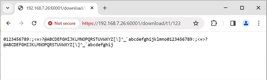
Figure 20 Increasing text pattern shown in web browser
Remark
· Our tested web browser is Google Chrome version 116.0.5845.141.
· The RSA certificate used in this demonstration is self-signed, meaning it was not issued by a certification authority (CA). When attempting to access the server with a self-signed certificate, the web browser may display a "Not Secure" alert.
· In case of downloading a binary pattern, a “Save as” dialog window appears. Users can save the file and view the binary data after the download process is complete.
For downloading existing files in server/log folder, users can input URL in the following format,
https://ip:port/download/log/filename
When user inputs https://192.168.7.26:60001/download/log/DG.html and DG.html exists in log folder. The secure connection is established, the html page is downloaded and displayed on the web browser, as shown in Figure 21.
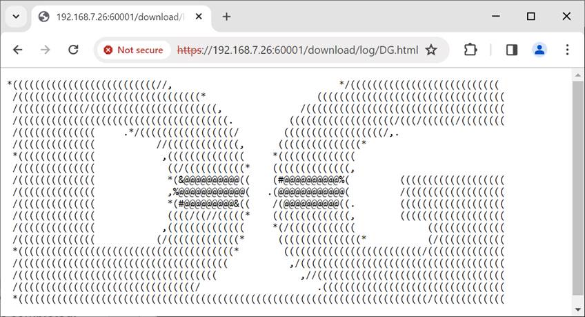
Figure 21 DG.html shown in web browser
Users can securely upload data through web browser by requesting uploadMenu.html from https://192.168.7.26:60001/upload/menu. Upload menu is displayed in the web browser, as shown in Figure 22. Users can select the data pattern and data length. The HTML page will prepare the data and send a POST command along with the data pattern to the server when the “POST” button is pressed. Because the length of the data is greater than or equal to 16,000 bytes, only the data length and transfer speed are displayed on server console when the upload is completed, as shown in Figure 23.
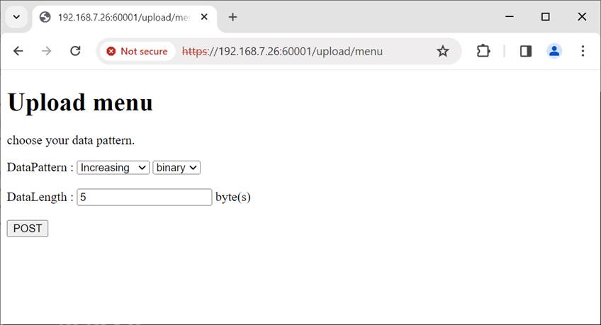
Figure 22 Secured upload page
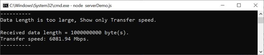
Figure 23 Server’s console when client upload large data
6 Board Setup
Follow these steps to set up the ZCU106 FPGA development board:
1) Make sure power switch is off and connect power supply to FPGA development board.
2) Connect two USB cables between FPGA board and PC via micro-USB ports.
3) Power on system.
4) Download configuration file and firmware to FPGA board by following step,
a) open Vivado TCL shell.
b) change current directory to download folder which includes demo configuration file.
c) Type “TLS10GCTest.bat”, as shown in Figure 24.
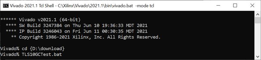
Figure 24 Example command script for download configuration file
Follow these steps to set up the KCU116 FPGA development board:
1) Make sure the power switch is off and connect the power supply to KCU116 development board.
2) Connect USB cable between PC to JTAG micro-USB port.
3) Power on the system.
4) Open Vivado Hardware Manager to program FPGA by following steps.
a) Click open Hardware Manager.
b) Open target -> Auto Connect.
c) Select FPGA device to program bit file.
d) Click Program device.
e) Click “…” to select program bit file.
f) Click Program button to start FPGA Programming.
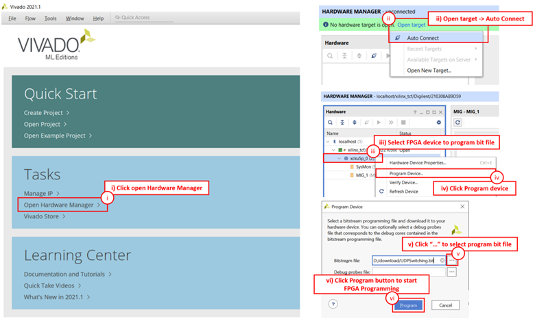
Figure 25 Program Device
7 Serial Console
Users can set the parameters, download and upload data by using the following command. The TLS10GCdemo commands and their usage will be displayed, as shown in Figure 26. Detailed information about each command is described in Topic 8 Command Details.
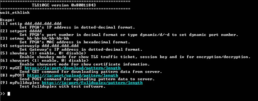
Figure 26 Serial console
8 Command Details
8.1 Set FPGA’s IP Address
command> setip ddd.ddd.ddd.ddd
This command is used to set FPGA’s IP address in dotted-decimal format. The default FPGA’s IP address is 192.168.11.42. Users can input setip command followed by a valid IP address.
8.2 Set FPGA’s Port Number
command> setport ddddd
This command is used to set the static port number of FPGA in decimal format. By default, the FPGA’s port number is set to be dynamic. Dynamic ports range from 49152 to 65535. Users can enable dynamic port again after specifying a port number by using “setport dynamic” command.
8.3 Set FPGA’s MAC address
command> setmac hh-hh-hh-hh-hh-hh
This command is used to set FPGA’s MAC address in hexadecimal format. The default FPGA’s MAC address is 00-01-02-03-04-05.
8.4 Set Gateway’s IP Address
command> setgatewayip ddd.ddd.ddd.ddd
This command is used to set gateway’s IP address in dotted-decimal format. The default gateway’s IP address is 192.168.11.2. Users can input setgatewayip command followed by a valid IP address.
8.5 Enable showkey mode
command> showkey <1: enable, 0: disable>
This command is used to enable showkey mode. When showkey mode is enabled, the TLS traffic ticket for encryption/decryption is displayed on the serial console, as shown in Figure 27. Users can use the TLS traffic ticket as (Pre)-Master-Secret log file for Wireshark* to decrypt transferred data between the client and server.
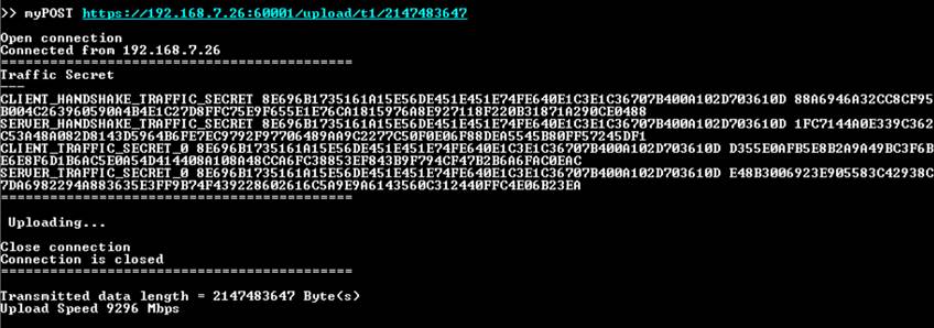
Figure 27 Serial console when showkey mode is enabled
*Wireshark, a network packet analyzer tool used for network troubleshooting, analysis, and security purposes.
8.6 Enable showcert mode
command> showcert <1: enable, 0: disable>
This command is used to enable showcert mode. When showcert mode is enabled, the server’s certificate stored in CertRam is displayed on the serial console, as shown in Figure 28. The certificate information is displayed in hexadecimal format, which corresponds to the result obtained by using openssl command: openssl x509 -in cert.pem -outform der | hexdump -C, as shown in Figure 29.
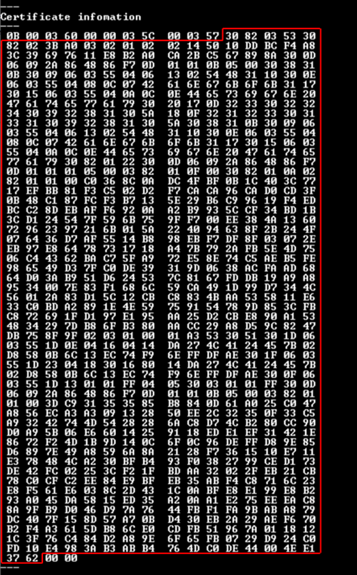
Figure 28 Serial console when showcert mode is enabled
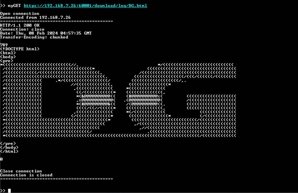
Figure 29 Certificate information from openssl command
8.7 Download data
command> myGET protocol://ip:port/download/pattern/length
This command simulates GET method of HTTP to download data from the server. Users can input a URL and then received data is displayed on the serial console. For download data pattern, the verification feature is enabled. If the received data matches the expected data, the total length of received data and download speed are displayed on the serial console.
In case of the downloaded data length exceeds 16kB, “Data Length is too large, Show only Transfer speed” is displayed instead of the received data, as shown in Figure 30.
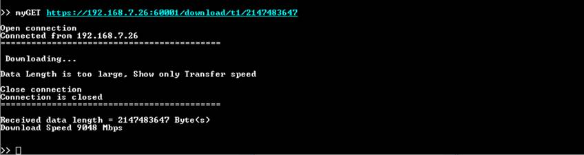
Figure 30 Serial console when downloading large data
Serial console when downloading large dataIn this demonstration, the maximum data length is limited at 2 GB for testing with the test software and 1 GB for testing with serverDemo.js, respectively. When users request to download data exceeding the maximum length, an error message is sent from server, causing the verification to fail, and the actual data and expected data will be displayed on the serial console.
For downloading HTML page, the verification feature is disabled. The received data is displayed on the serial console, as shown in Figure 31.

Figure 31 Serial console when downloading DG.html
8.8 Upload data
command> myPOST protocol://ip:port/upload/pattern/length
This command simulates POST method of HTTP to upload data to the server. Users can specify the data pattern and data length in the URL. After the upload is completed, the data length and upload speed are displayed, as shown in Figure 32 and Figure 33. On the server’s console, the number of data sent from the client and transfer speed is displayed. If the data length is less than 16 kB, the received data is also displayed, as shown in Figure 34.
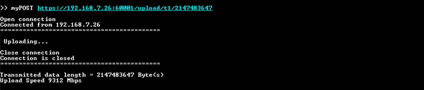
Figure 32 Serial console when uploading large data
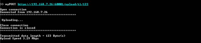
Figure 33 Serial console when uploading 123-byte data
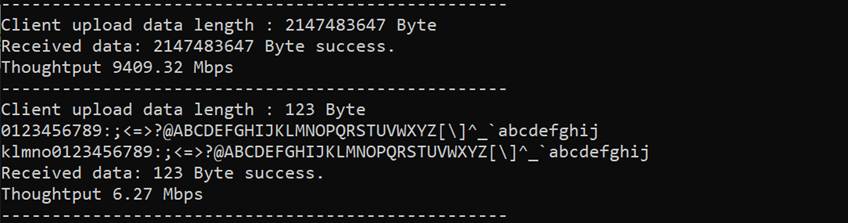
Figure 34 Server console when uploading 123-byte data
8.9 Full duplex test
command> myFullduplex protocol://ip:port/fullduplex/pattern/length
This command is used to transfer data between the client and server in full duplex mode. It simulates POST method of HTTP with the fullduplex URL, which requests a data pattern from the server and uploads the data pattern to the server. Users can specify the data pattern and data length in the URL. After the transmission and reception of data are complete, the data length and transfer speed are displayed, as shown in Figure 35.
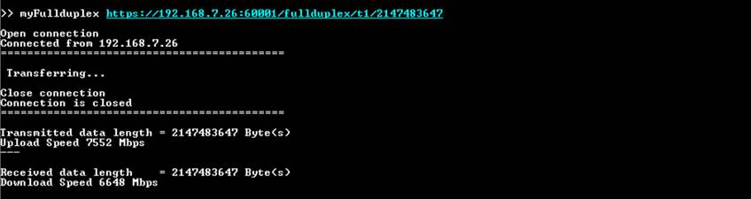
Figure 35 Serial console when full duplex mode is tested
9 Test setup when using 2 FPGA boards
9.1 Environment setup when using 2 FPGA boards
To operate TLS10GC-IP demo with TLS10GS-IP demo, please prepare following test environment.
1) FPGA development boards (ZCU106 as a client and ZCU102 as a server).
2) 10 Gb Ethernet cable:
a) 10 Gb SFP+ Passive Direct Attach Cable (DAC) which has 1-m or less length
b) 10 Gb SFP+ Active Optical Cable (AOC)
c) 2x10 Gb SFP+ transceiver (10G BASE-R) with optical cable (LC to LC, Multimode)
3) Micro USB cable for JTAG connection connecting between FPGA board and Test PC.
4) 2 Micro USB cable for UART connection connecting between ZCU102 board and Test PC and between ZCU106 board and Test PC.
5) Vivado tool for programming FPGA installed on Test PC.
6) Serial console software such as TeraTerm installed on PC. The setting on the console is Baudrate=115200, Data=8-bit, Non-parity and Stop=1.
7) Batch file named TLS10GCIPTest.bat” and TLS10GSIPTest.bat” (To download these files, please visit our web site at www.design-gateway.com)
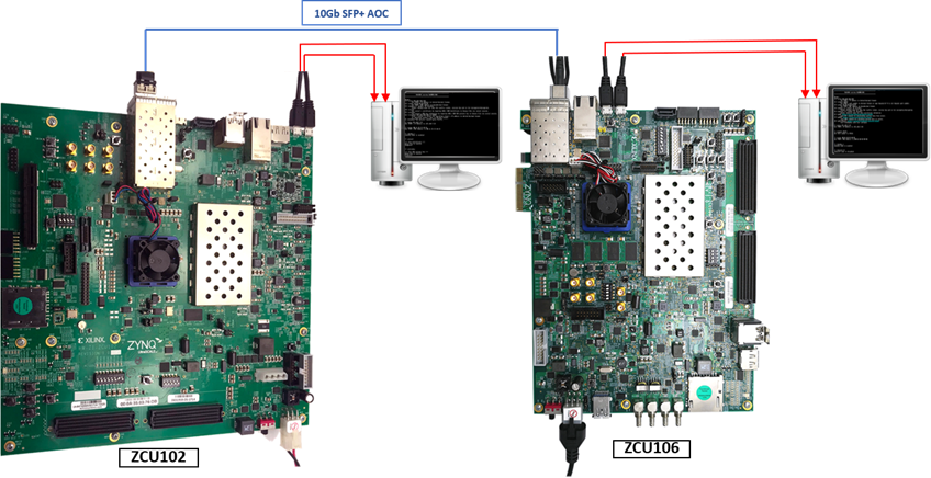
Figure 36 TLS10GC-IP demo environment when using 2 FPGA boards
Follow step 1)-8) of Topic 6 Board Setup to prepare FPGA boards for running the demo. Run “TLS10GCTest.bat” to download configuration file and firmware to ZCU106 board as a client and run “TLS10GSTest.bat” to download configuration file and firmware to ZCU102 board as a server. The details of supported commands and their usage for TLS10GC-IP demo is described in the following link.
https://www.dgway.com/products/IP/TLS-IP/TLS10GSIP-instruction-xilinx-en/
9.2 Test sequence
9.2.1 Set parameters and start a server
1) Set network parameters of each FPGA board: IP address, port number, and mac address.
2) Set server’s certificate and RSA key information via serial console of server.
3) Start a server, as shown in Figure 37 by entering the following command in server’s console:
listenFor <client’s IP address> on <server’s port number>
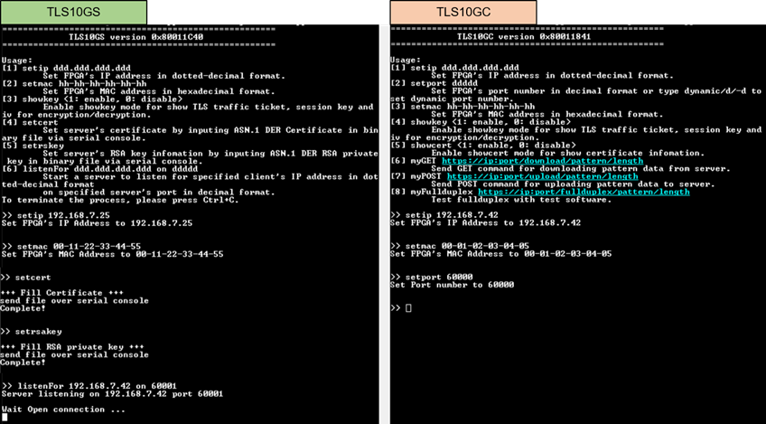
Figure 37 Server and client console when parameters are set
9.2.2 Transmit data test (Server to client)
Enter the command myGET protocol://ip:port/download/pattern/length through client’s console to request the data pattern from TLS10GS demo. Once the data transfer is complete, the transfer results and speed will be presented on both client’s and server’s consoles, as shown in Figure 38.
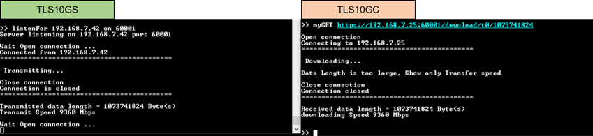
Figure 38 Server and client console when transfer data from server to client
9.2.3 Receive data test (Client to server)
Enter the command myPOST protocol://ip:port/upload/pattern/length through client’s console to transmit the data pattern from TLS10GC demo to TLS10GS demo. Once the data transfer is complete, the transfer results and speed will be presented on both client’s and server’s consoles, as shown in Figure 39.
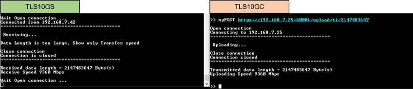
Figure 39 Server and client console when transfer data from client to server
9.2.4 Full duplex test
Enter the command myFullduplex protocol://ip:port/fullduplex/pattern/length through client’s console to test transfer data in full duplex mode between TLS10GS demo and TLS10GC demo. Once the data transfer is complete, the transfer results and speed will be presented on both client’s and server’s consoles, as shown in Figure 40.
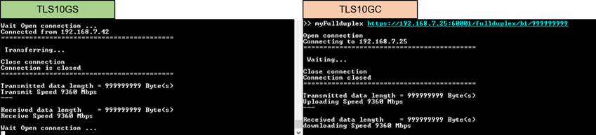
Figure 40 Server and client console when transfer data in full duplex mode
10 Test results
This demonstration, TLS10GCdemo is showcased for its ability to function as a secure client. The HTTPS protocol is chosen as the application layer to demonstrate that TLS10GC-IP can implement TLS1.3 to secure HTTP communication. The subsequent section details the test results when transferring data between each component, covering 2 main aspects: functionality testing and performance testing.
10.1 Functionality testing
TLS10GCdemo is designed to send HTTPS request to a server, demonstrating that TLS10GC-IP can handle TLS1.3 connection similar to a web browser. As shown in Figure 41 and Figure 42, a web browser requests a data pattern via the GET command and displays the received HTTP payload from the server on the browser, producing the same result on the serial console of TLS10GCdemo.
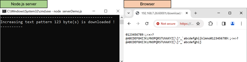
Figure 41 Test results when web browser download data from node.js server
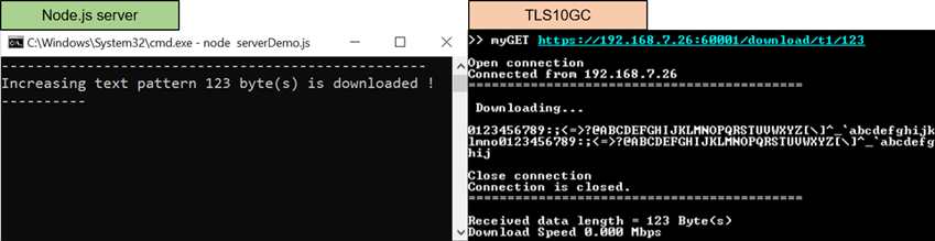
Figure 42 Test results when TLS10GCdemo download data from node.js server
In the case of uploading data, TLS10GCdemo is capable of transmitting a data pattern with HTTP header to the server. The receiving results shown on the server console upon completing the reception of data from TLS10GCdemo, as shown as Figure 43, are similar to when receiving data from a web browser, as shown as Figure 44.
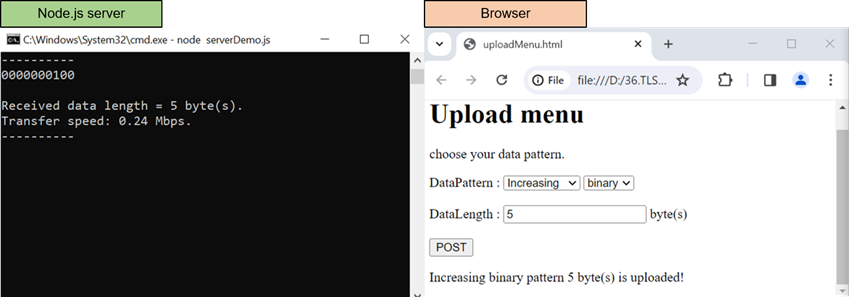
Figure 43 Test results when web browser upload data to node.js server
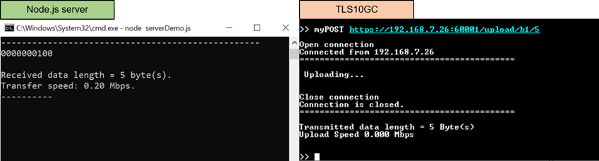
Figure 44 Test results when TLS10GCdemo upload data to node.js server
10.2 Performance testing
When the example node.js server is used as a server to communicate with TLS10GCdemo, the CPU manages encryption/decryption during data transfer, causing a decrease in transfer speed. To achieve the maximum throughput, the "server" application is used instead.
“Server” application is designed to encrypt data before transmission through the network in Tx mode, decrypt the last data block and verify the total received data size only in Rx mode. As shown in Figure 45 and Figure 46, the transfer speed is nearly by 10 Gbps and the utilization of the Intel i7 CPU is approximately 100%, as monitored by the PC's task manager. This indicates that if the CPU is tasked with encrypting/decrypting data while transferring data through the network, the transfer speed will be reduced.
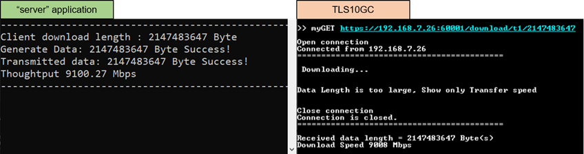
Figure 45 Test results when TLS10GCdemo upload data to node.js server
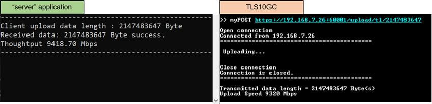
Figure 46 Test results when TLS10GCdemo upload data to “server” application
For full duplex mode, the transfer speed between “server” application and TLS10GCdemo decreases, as shown in Figure 47. This suggests that the CPU cannot handle both receiving and transmitting task in a secure connection to maintain the 10 Gbps throughput.
In the testing scenario between two FPGA boards, where TLS10GCdemo acts as a client and TLS10GSdemo as a server, cryptographic tasks, including encryption/decryption, are entirely offloaded to hardware. As shown in Figure 48, the throughput increases to 9360 Mbps, representing the maximum throughput achievable with TCP/IP in this demonstration.
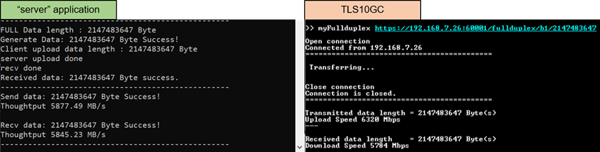
Figure 47 Full duplex test results between TLS10GCdemo and “server” application

Figure 48 Full duplex test results between TLS10GSdemo and TLS10GCdemo
11 Revision History
|
Revision |
Date (D-M-Y) |
Description |
|
1.03 |
2-Apr-25 |
Add setgatewayip command |
|
1.02 |
5-Mar-24 |
Add test results between 2 FPGA boards |
|
1.01 |
22-Dec-23 |
Add full duplex test |
|
1.00 |
8-Sep-23 |
Initial version release |