TLS10GS-IP Core Datasheet

Core Facts |
|
|
Provided with Core |
|
|
Documentation |
User Guide, Design Guide |
|
Design File Formats |
Encrypted File |
|
Instantiation Templates |
VHDL |
|
Reference Designs & Application Notes |
Vivado Project, See Reference design manual |
|
Additional Items |
Demo on ZCU106, ZCU102 |
|
Support |
|
|
Support Provided by Design Gateway Co., Ltd. |
|
Design Gateway Co.,Ltd
E-mail: ip-sales@design-gateway.com
URL: design-gateway.com
Features
· support TLS1.3 cipher suite: TLS_AES_256_GCM_SHA384
· Key exchange: X25519
· Derive key: HKDF with SHA384
· Encryption/decryption: AES256GCM
· Certificate type: RSA2048
· Signature algorithm: rsa_pss_rsae_sha256
· Recommend clock frequency at least 180 MHz for highest throughput
· Customized service for following features
· Certificate size extension
· Customized user interface to AXI-interface
Table 1: Example Implementation Statistics
|
Family |
Example Device |
Fmax (MHz) |
CLB Regs |
CLB LUTs |
CLB1 |
IOB |
BRAMTile |
Design Tools |
|
Zynq-Ultrascale+ |
xczu7ev-ffvc1156-2-e |
220 |
11861 |
31015 |
5979 |
- |
83 |
Vivado2022.1 |
Notes:
1) Actual logic resource dependent on percentage of unrelated logic
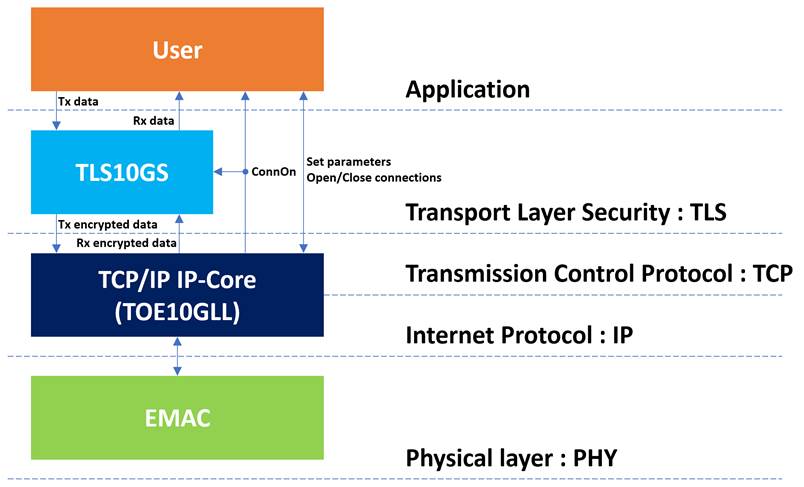
Figure 1: TLS protocol architecture
General Description
Transport Layer Security (TLS) is a cryptographic protocol that establishes a secure connection between a client and a server over the network. TLS is widely used in secure web browsing, email, file transferring, voice-over-IP, etc.
Before transferring payload using the TLS protocol, the handshake process is initiated to exchange and generate encryption/decryption keys, ensuring data privacy (confidentiality). Additionally, TLS Server signs server’s certificate and sends the signature to the client to provide authenticity.
TLS1.3 Server 10Gbps IP Core (TLS10GS-IP) is designed to handle the TLS1.3 handshake for server, encrypt payload before transmission, and decrypt application data. After the TCP connection is established by TCP/IP offload engine and ClientHello message from client is received, the TLS handshake process is started. After the handshake is completed, users can write plain TxData to UserTxBuffer or read plain RxData from UserRxBuffer with a circular buffer concept.
Transport Layer Security Protocol Version 1.3 and some technical terms referenced in this document, are defined following RFC8446 standard. For further information about TLS1.3 standard, please refer to the following the link. https://datatracker.ietf.org/doc/html/rfc8446
Functional Description
TLS10GS-IP interface signals can be divided into 2 parts, i.e., user interface signals and TCP/IP interface signals, as shown in Figure 2. Users can control and transfer data with TLS10GS-IP via the user interface signals as described in Table 2.
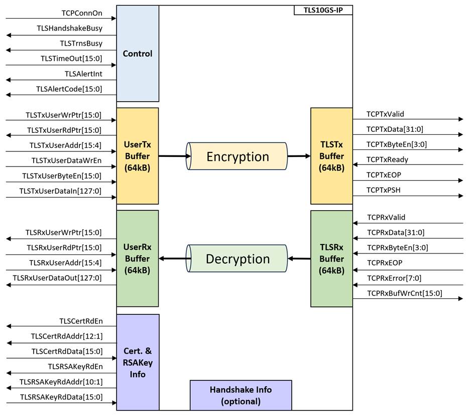
Figure 2: TLS10GS-IP block diagram
Table 2: User Interface signals
|
Signal name |
Dir |
Description |
|
RstB |
In |
IP core system reset. Active low. |
|
TLSClk* |
In |
IP core system clock. |
|
TCPTxClk |
In |
Clock signal which is synchronous to TCP Tx interface. |
|
TCPRxClk |
In |
Clock signal which is synchronous to TCP Rx interface. |
|
version[31:0] |
Out |
32-bit version number of TLS10GS-IP. |
|
TestPin[31:0] |
Out |
Reserved for internal use |
|
Control interface |
||
|
TCPConnOn |
In |
Connection Status. ‘1’: connection is active, ‘0’: no connection. |
|
TLSHandshakeBusy |
Out |
TLSHandshakeBusy specifies the busy status of handshake operation. |
|
TLSTrnsBusy |
Out |
TLSTrnsBusy specifies the busy status of data transfer operation. |
|
In |
Timeout value for waiting the packet returned from the target device before returning TLSAlertCode. Valid from 0x0000 – 0xFFFF. Timescale is approximately 896k clocks of TLSClk. |
|
|
TLSAlertInt |
Out |
Alert Interrupt. Asserted to ‘1’ for one cycle when alert is detected. |
|
TLSAlertCode[15:0] |
Out |
Alert code indicates normal and alert conditions. TLSAlertCode[15:8] and TLSAlertCode[7:0] indicate AlertLevel and AlertDescription, respectively. |
|
User Tx interface** |
||
|
TLSTxUserWrPtr[15:0] |
In |
TLSTxWrPtr is the write pointer where the user indicates the position after the last byte written. |
|
TLSTxUserRdPtr[15:0] |
Out |
TLSTxRdPtr is the read pointer where IP indicates the first byte position to process. |
|
TLSTxUserAddr[15:4] |
In |
Address input to write data memory. |
|
TLSTxUserDataWrEn |
In |
Asserted to ‘1’ when TLSTxDataIn is valid. |
|
TLSTxUserByteEn[15:0] |
In |
Byte enable input to mask the TLSTxDataIn port so that only specific bytes of the data are written. |
|
TLSTxUserDataIn[127:0] |
In |
DataIn is 128-bit input data. |
|
User Rx interface** |
||
|
TLSRxUserWrPtr[15:0] |
Out |
TLSRxWrPtr is the write pointer where the IP indicates the position after the last byte written. |
|
TLSRxUserRdPtr[15:0] |
In |
TLSRxRdPtr is the read pointer where the user indicates the first byte position to read. |
|
TLSRxUserAddr[15:4] |
In |
Address input to read data memory. |
|
TLSRxUserDataOut[127:0] |
Out |
DataOut is 128-bit output data. |
|
Server certificate and RSA private key file |
||
|
TLSCertRdEn |
Out |
Asserted to ‘1’ as Read Enable when reading TLSCertRdData. |
|
TLSCertRdAddr[12:1] |
Out |
Read Address for reading TLSCertRdData.Valid when TLSCertRdEn=’1’. |
|
TLSCertRdData[15:0] |
In |
TLSCertRdData is 16-bit input data of server’s certificate. This signal must be valid after TLSCertRdEn is asserted to be ‘1’ and corresponding to TLSCertRdAddr. |
|
TLSRSAKeyRdEn |
Out |
Asserted to ‘1’ as Read Enable when reading TLSRSAKeyRdData. |
|
TLSRSAKeyRdAddr[10:1] |
Out |
Read Address for reading TLSRSAKeyRdData. Valid when TLSRSAKeyRdEn=’1’. |
|
TLSRSAKeyRdData[15:0] |
In |
TLSRSAKeyRdData is 16-bit input data of RSA private key. This signal must be valid after TLSRSAKeyRdEn is asserted to be ‘1’ and corresponding to TLSRSAKeyRdAddr. |
|
TLS handshake information*** |
||
|
TLSKeyValid |
Out |
Asserted to ‘1’ when key materials are valid. |
|
Random[255:0] |
Out |
256-bit Random number in ClientHello. Valid when TLSKeyValid is asserted to ‘1’. |
|
CTS[383:0] |
Out |
Client Traffic Secret is key material to derive TkcKey and TkcIv. Valid when TLSKeyValid is asserted. |
|
STS[383:0] |
Out |
Server Traffic Secret is key material to derive TksKey and TksIv. Valid when TLSKeyValid is asserted. |
|
TCP Tx Interface (Synchronous to TxClk) |
||
|
TCPTxValid |
Out |
Asserted to ‘1’ when TCPTxData is valid. |
|
TCPTxData[31:0] |
Out |
Transmitted TCP data. Valid when TCPTxValid=‘1’. |
|
TCPTxByteEn[3:0] |
Out |
Byte enable of TCPTxData. Valid when TCPTxValid=‘1’. The signal can be equal to four values – “0001”, “0011”, “0111” or “1111” when TCPTxData[7:0], [15:0], [23:0] or [31:0] is valid respectively for any data in the packet. |
|
TCPTxReady |
In |
TCP ready to receive data. ‘0’ when not ready to receive data, ‘1’ when ready to receive data. |
|
TCPTxEOP |
Out |
Asserted to ‘1’ with the final data of the packet on TCPTxData. Valid when TCPTxValid is asserted to ‘1’. |
|
TCPTxPSH |
Out |
PSH flag asserted in TCP header of this packet. |
|
TCP Rx Interface (Synchronous to RxClk) |
||
|
TCPRxValid |
In |
Asserted to ‘1’ when TCPRxData is valid. |
|
TCPRxData[31:0] |
In |
Received TCP data. Valid when TCPRxValid=‘1’ |
|
TCPRxByteEn[3:0] |
In |
Byte enable of TCPRxData. Valid when TCPRxValid=‘1’. During packet transmission, this signal is equal to “1111” for enabling all 32-bit data except the final data of the packet which can be equal to four values – “0001”, “0011”, “0111”, or “1111” when TCPRxData[7:0], [15:0], [23:0], or [31:0] is valid respectively. |
|
TCPRxEOP |
In |
End of packet. Asserted to ‘1’ while the final TCPRxData is valid. |
|
TCPRxError[7:0] |
In |
Error status of the received packet. Valid at the end of packet (TCPRxEOP=’1’ and TCPRxValid=’1’). If TCPRxError is not 0x00 at the end of packet, the whole packet of data is discarded. |
|
TCPRxBufWrCnt[15:0] |
Out |
The number of unprocessed data in TCPRxBuffer for TCP/IP offload engine to calculate free space size. |
Note:
* To handle 10Gbps ethernet speed, the recommended clock frequency of TLSClk is at least 180 MHz.
** TLS10GS-IP can provide AXI-interface for Data Interface upon request.
*** TLS handshake information is optional signals that user can access handshake information in details. User can ignore these signals and implement TLS10GS-IP as a channel to pass through payload.
· Handshake process
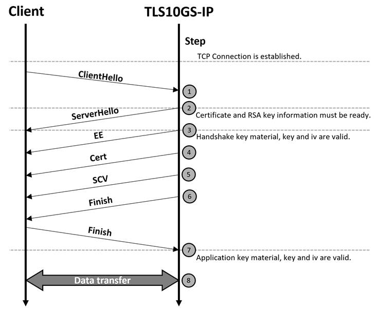
Figure 3: Handshake process
Figure 3 shows the main flow of TLS1.3 full handshake process. Once the TCP connection is established and ClientHello message from the client is received, TLS10GS-IP, as a server, checks the supported TLS parameters including the supported cipher suite, which must be TLS_AES_256_GCM_SHA384, compression method, signature algorithm, support version, Client’s public key and client’s max fragment. If all parameters are valid and supported, TLS10GS-IP responds by transmitting a ServerHello message, which including the server’s ephemeral X25519 public key.
After sending ServerHello message, the secure connection is established. All messages, including handshake messages and user’s payload, are encrypted before being transferred through the network using AES256GCM.
When TLS10GS-IP receives ClientHello message, the client’s public key is used to compute the keyshared with X25519. This keyshared will be passed to a key derivation function to generate the key materials for encryption/decryption. For TLS10GS-IP, the supported key derivation function is the Hash-based Key Derivation Function (HKDF) with SHA384.
TLS10GS-IP uses HKDF-SHA384 to generate two key materials, Client Traffic Secret (CTS) and Server Traffic Secret (STS). First, CTS is used to derive the client traffic key and initialization vector (IV) to encrypt handshake messages sent by the client. STS is used to derive the server traffic key and IV to decrypt handshake messages sent by the server. Users can access CTS and STS when TLSKeyValid is asserted to ‘1’.
TLS10GS-IP supports maximum fragment length negotiation from clients. By default, the maximum fragment length is set to 16kB. If TLS10GS-IP receives a ClientHello message containing the max_fragment_length extension, the maximum fragment length will be set corresponding to the valid values of the field, which are 512B, 1kB, 2kB and 4kB.
To provide authenticity through the server’s certificate and RSA2048-PSS with SHA256 signature, users must prepare the server’s certificate and RSA private key file for TLS10GS-IP in ASN.1 DER binary encoding. The maximum size is 8 kB for the certificate and 2 kB for the RSA private key file.
As shown in Figure 4, TLS10GS-IP will assert TLSCertRdEn to ‘1’ and set TLSCertRdAddr[12:1] as the read address to read the certificate data (TLSCertRdData[15:0]). TLS10GS-IP will start reading at TLSCertRdAddr[12:1]=0 until the end of the data corresponding to the length indicated at the beginning of ASN.1 DER data. Users can use TLSCertRdAddr[12:1] and TLSCertRdEn as control signals for reading data from the buffer.
In the same way, TLS10GS-IP will access the RSA key information corresponding to ASN.1 DER structure. TLSRSAkeyRdEn is asserted to ‘1’ and TLSRSAKeyRdAddr[10:1] is set as the read address to read the RSA key information (TLSRSAkeyRdData[15:0]), as shown in Figure 5.
TLS10GS-IP may be not read the certificate or RSA key information in order, TLSCertRdData[15:0] and TLSRSAkeyRdData[15:0] must be valid after 1 clock cycle corresponding to TLSCertRdAddr[12:1] and TLSRSAKeyRdAddr[10:1], respectively.
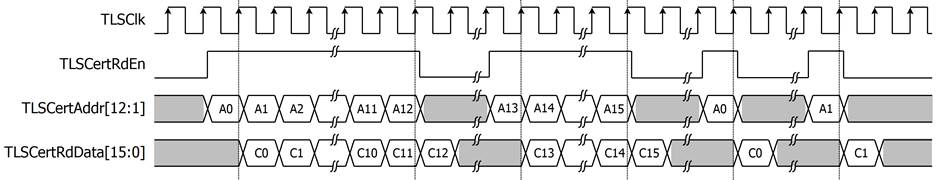
Figure 4: Example of timing diagram for reading certification information
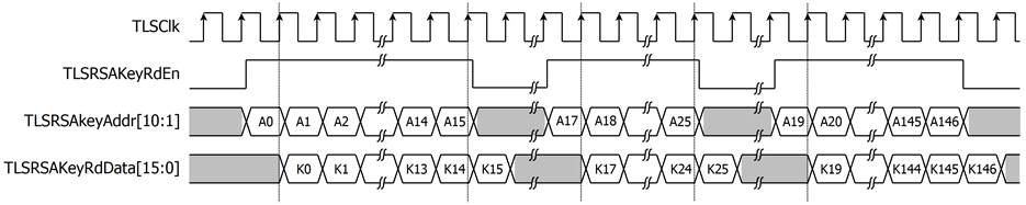
Figure 5: Example of timing diagram for reading RSA key information
After receiving client’s finished message, TLS10GS-IP regenerates key materials, namely CTS and STS, to derive key and IV for application data. TLSKeyValid is de-asserted to ‘0’ while the key derivation is in progress. After the key derivation is completed, TLSKeyValid is asserted to ‘1’ to indicate that CTS and STS are valid, as shown in Figure 6.
TLS10GS-IP is designed to handle the full handshake process with the supported cipher suite, encrypt and decrypt data through the network. The session resumption feature is not supported. Opening and closing connections are managed by the user. TLS10GS-IP monitors TCP status via TCPConnOn. As shown in Figure 6, after the TCP connection is established, indicated by the rising edge of TCPConnOn, TLS10GS-IP starts the handshake operation, TLSHandshakeBusy is asserted to ‘1’. Before the handshake process is completed (TLSHandshakeBusy is deasserted to ‘0’), the user can prepare TxData to UserTxBuffer. As soon as the handshake process is complete and there is available data in UserTxBuffer, TLS10GS-IP is operating in the data transfer phase. While there is RxData that has not been processed in TCPRxBuffer or Tx operation is in progress, TLSTrnsBusy is asserted to ‘1’. To terminate the connection because of finishing communication or receiving alert codes, the user can send closing command to TCP/IP offload engine to close connection. TLSAlertCode is designed to indicate the normal and alert conditions of TLS10GS-IP. When the connection is established (TCPConnOn = ‘1’), TLSAlertCode is reset to 0x0000, as shown in Figure 6. When TLSAlertCode is set, TLSAlertCodeInt is asserted to be ‘1’. The details of each alert code are described in section Alert handling.
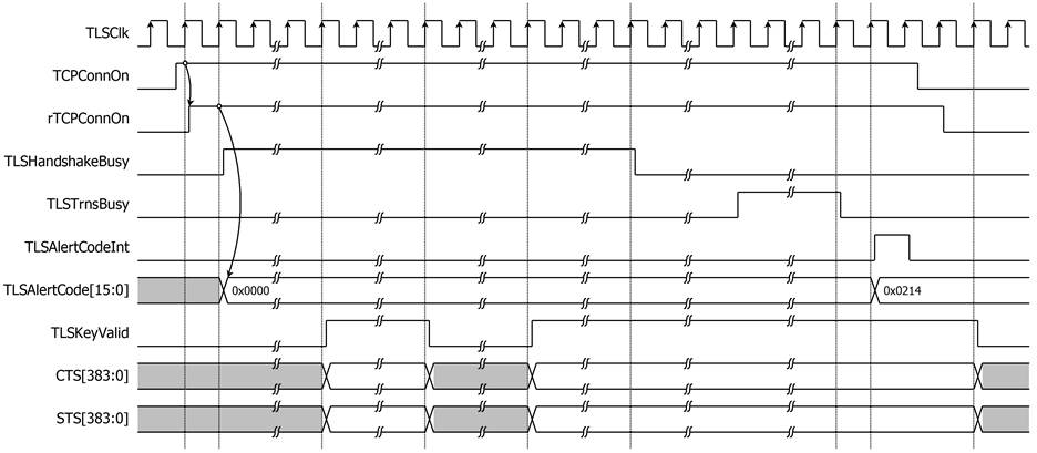
Figure 6: Example of control signal in handshake process timing diagram
· Alert handling
In TLS1.3 protocol, the sender can send alert message to indicate receiver closure information and errors. TLS10GS-IP is designed to support alert message, as shown in Table 3.
Table 3: Alert code and description
|
No. |
Alert Code |
Alert Message |
Description |
|
1 |
0x0100 |
close_notify |
Receive Notification that the sender will not send any more messages on this connection. |
|
2 |
0x020A |
unexpected_message |
Received out-of-sequence message: the packet type of received handshake packet is not matched to the expected packet type. |
|
3 |
0x0214 |
bad_record_mac |
Received an encrypted packet, in handshake phase or data transfer phase, with an invalid tag. |
|
4 |
0x0228 |
handshake_failure |
Indicate that the sender was unable to negotiate an acceptable set of security parameters given the options available. For example, TLS10GS-IP validates ClientHello message and finds that the client’s cipher suites do not include TLS_AES_256_GCM_SHA384 or support version is not TLS 1.3 |
|
5 |
0x022F |
illegal_parameter |
Received the max_fragment_length extension with an invalid value or compression method is not zero. |
|
6 |
0x0232 |
decode_error |
A message could not be decoded because some fields were out of the specified ranges, or the length of the message was incorrect. |
|
7 |
0x0233 |
decrypt_error |
Failed handshake cryptographic operation: unable to correctly verify a signature or validate a finished message. |
|
8 |
0x0250 |
Internal_error |
Received packet that exceeds the length limit of internal buffer. |
|
9 |
0x0251 |
timeout_alert |
Indicate that the timeout is met for waiting the packet returned from the target device. |
|
10 |
0x0252 |
abnormal_close |
Indicate that the connection is abnormally closed while TLS10GS-IP is handling handshake process or transferring TxData. |
|
11 |
0x0253 |
unsupported_format |
Indicate that certificate or RSA key information is prepared in unsupported format. |
For the fatal alert level (AlertCode[15:8]=0x02), the connection will be closed. TLS10GS-IP is designed to handle alert messages in two ways based on who sends the closure information and errors.
In case of the server sending the alert messages, according to opening and closing the connection is handled by TCP/IP offload engine. When TLS10GS-IP detects alert No.2-11, TLSAlertInt is asserted to ‘1’ and TLSAlertCode is set following the conditions shown in Table 3. TLS10GS-IP will send an alert message to the client, and the user is required to send a close connection command to the TCP/IP offload engine to close the connection, as shown in Figure 7.
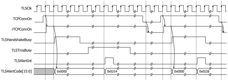
Figure 7: Alert signals behavior in case of server send alert message
In case of client sending the alert messages, client will also close the connection, which results in TCPConnOn de-asserted to ‘0’. TLS10GS-IP will stop sending data to TCP (stop Tx operation) and process only Rx operation until the alert message sent by client is found or there is no available data in RxBuffer. Once TLS10GS-IP finds the alert message, TLSAlertCode is set to the alert code from alert message and TLSAlertInt is asserted to ‘1’, as shown in Figure 8.
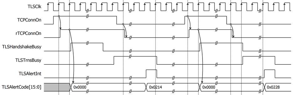
Figure 8: Alert signals behavior in case of client send alert message
In case of receiving close_notify from client, the connection is not closed. TLSAlertInt is asserted to ‘1’ and TLSAlertCode is set to 0x0100 (close_notify). Rx data after close_notify alert will not be processed following RFC8446 standard. If there are available TxData in UserTxBuffer, Tx operation still processes until user sends close command to TCP/IP offload engine, as shown in Figure 9.
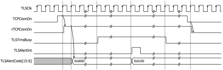
Figure 9: Alert signals behavior in case of receiving close_notify message
If the connection is closed while Tx operation is processing and TLS10GS-IP cannot find any alert message from client, TLSAlertCode is set to abnormal_close (0x0252), and TLSAlertInt is asserted to ‘1’, as shown in Figure 10.
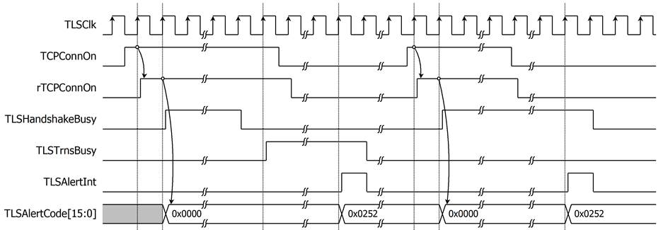
Figure 10: Alert signals behavior in case of abnormal_close
· User Tx interface
The circular buffer concept is applied to prepare Tx Data. The position of available data is indicated by write pointer (WrPtr) and read pointer (RdPtr). WrPtr points to the next address in byte unit to write and RdPtr points to the next address in byte unit to read. When RdPtr points to the same address as WrPtr, it means this circular buffer is empty, as shown in Figure 11a. For example, if WrPtr points to address 6 and RdPtr points to address 2, as shown in Figure 11b, that means 4-byte data are available from address 2 to 5. When RdPtr points at WrPtr-1, it means this circular buffer is full, as shown in Figure 11c.
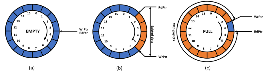
Figure 11: Example of write pointer and read pointer of circular buffer
TLSTxUserWrPtr[15:0] is used as WrPtr and TLSTxUserRdPtr[15:0] is used as RdPtr. When the connection is established (TCPConnOn = ‘1’), TLSTxUserRdPtr[15:0] is set to the same address as TLSTxUserWrPtr[15:0] to clear data in UserTxBuffer for the new connection. User can prepare Tx Data for sending through the network by writing data via ram interface (using TLSTxUserDataWrEn, TLSTxUserDataIn[127:0], TLSTxUserAddr[15:4] and TLSTxUserByteEn[15:0]). Then user moves TLSTxUserWrPtr[15:0] to indicate TLS10GS-IP that there are available data in UserTxBuffer. Then TLS10GS-IP operates in data transfer phase, the TxData as much as available in buffer memory will be encrypted and transmitted as most as TLS maximum packet size which follows max fragment length.
For example, user writes 68-byte data to UserTxBuffer at address TLSTxUserAddr[15:4]=0x00-0x04 and moves TLSTxUserWrPtr to 0x44. It means that there are 68-byte data available in UserTxBuffer. TLS10GS-IP operates 68-bytes data and moves TLSTxUserRdPtr to 0x44 to indicate that 68-bytes TxData is already operated, as shown in Figure 12. When user wants to send next 45-byte data, TLSTxUserDataIn[127:0] is written to TLSTxUserAddr=0x04 and TLSTxUserByteEn[3:0] is set to 0xFFF0 to start writing at address 0x44 in byte unit. User must start writing the next data at TLSTxUserWrPtr, as shown in Figure 12.
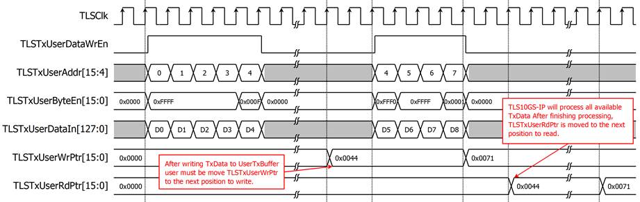
Figure 12: Example timing diagram for writing data 68 and 45 bytes to TLS10GS-IP
· TCP Tx interface
When there are available TxData from user, Tx operation is started. TxData is encrypted to 64kB-Buffer, called TLSTxBuffer, and transferred from TLSTxBuffer to TCP/IP offload engine via simple streaming data interface. TCPTxValid and TCPTxByteEn[3:0] is used for indicating that which byte of TCPTxData[31:0] is valid. As shown in Figure 13, when TCPTxData (D0-D25) is valid 4 bytes, TCPTxByteEn[3:0] is set to 0xF. When TCPTxData (D26) is valid only 2 bytes, TCPTxByteEn[3:0] is set to 0x3. In case of TCP/IP offload engine is not ready to receive new TxData (TCPTxReady=’0’), TCPTxValid, TCPTxByteEn and TCPTxData are hold the same value (0xF and D32, respectively) until TCPTxReady is asserted to ‘1’. TCPTxEOP and TCPTxPSH is asserted to ‘1’ at the last clock of data to indicate the end of packet and set push flag to TCP packet, respectively.
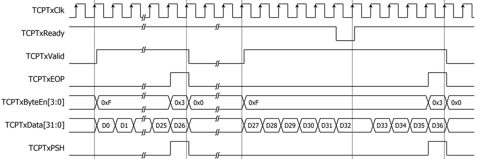
Figure 13: Example timing diagram of TLS10GS-IP transmits 106 bytes and 38 bytes to TCP/IP
· TCP Rx interface
TLS10GS-IP is designed to receive RxData from TCP/IP offload engine via simple streaming data interface and store RxData in 64kB-buffer, called TLSRxBuffer. TLS10GS-IP uses TCPRxByteEn[3:0] and TCPRxValid to indicate that which byte of TCPRxData[31:0] is valid. When there are RxData transferred from TCP/IP offload engine, TCPRxBufWrCnt[15:0] is increased by the number of received data. TCPRxBufWrCnt[15:0] shows the number of data which are not processed in TLSRxBuffer and can be used for computing the window size returned to target device in TCP ACK packet. When there are available RxData in TLSRxBuffer, Rx operation is started. RxData in TLSRxBuffer will be decrypted and the decrypted RxData is written in UserRxBuffer. After that TCPRxBufWrCnt[15:0] is decreased by the number of decrypted data, as shown in Figure 14.
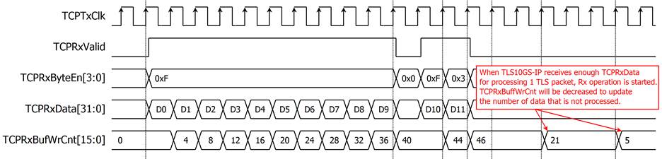
Figure 14: Example timing diagram of TLS10GS-IP receives data 40 bytes and 6 bytes from TCP/IP
· User Rx interface
The circular buffer concept is also applied to Rx Buffer. TLSRxUserWrPtr[15:0] is used as WrPtr and TLSRxUserRdPtr[15:0] is used as RdPtr. When the TCPConnOn is asserted to ‘1’, TLSRxUserWrPtr[15:0] is set to the same address as TLSRxUserRdPtr[15:0] to clear data in UserRxBuffer for the new connection. User can read data via Ram interface (using TLSRxUserDataOut[127:0] and TLSRxUserAddr[15:4]) and move TLSRxUserRdPtr[15:0] to indicate the last address of data that user already processed. For example, TLSRxUserWrPtr is moved to 0x31. When user have already processed 49-byte data, user can set TLSRxUserRdPtr to 0x31 for releasing UserRxBuffer, as shown in Figure 15. When there are enough RxData to process in TLSRxBuffer and available space in UserRxBuffer more than half (32kB), TLS10GS-IP will process the RxData and then write to UserRxBuffer. After that TLSRxUserWrPtr[15:0] is set to the next position to write. As shown in Figure 15, after TLS10GS-IP has operated next 47-byte data, TLSRxUserRdPtr is moved to 0x60.
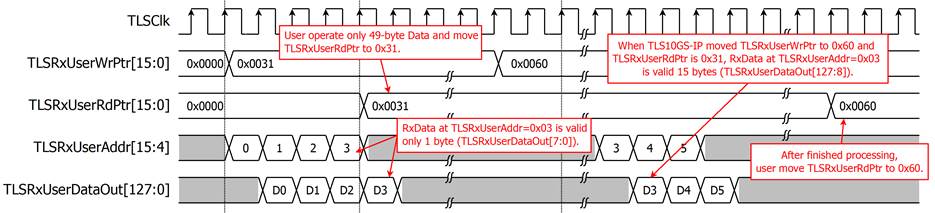
Figure 15: Example of user access RxData 49 bytes and 47 bytes from TLS10GS-IP timing diagram
· Tx/Rx operation management
In data transfer phase, TLS10GS-IP handles Tx operation and Rx operation determined by the numbers of unprocessed data. TLS10GS-IP will process the operation that has more unprocessed data. If the amount of data in UserTxBuffer is more than in TLSRxBuffer and there is enough space available in UserTxBuffer (32kB), Tx operation is started to encrypt and transfer to TCP/IP offload engine. In the same way, if the amount of data in TLSRxBuffer is greater than or equal to the number of UserTxBuffer and there is enough space available in UserRxBuffer (32kB), Rx operation is started to decrypt 1 TLS packet, store in UserRxBuffer and move TLSRxUserWrPtr.
Caution:
- In case of Rx operation is started but there are not enough data in TLSRxBuffer to complete 1 TLS packet corresponding to the value specified in the TLS packet header, TLS10GS-IP will wait for incoming data until timeout is met.
- In case of TCP connection is closed (TCPConnOn =’0’) while TLS10GS-IP operates data transfer operation (TLSTrnsBusy=’1’), Tx operation will be terminated and TLS10GS-IP will process only RxData until alert code is found or timeout is met. Then TLS10GS-IP will clear the remaining data in TLSTxBuffer and TLSRxBuffer and de-assert TLSTrnsBusy to be ‘0’. The new connection MUST NOT be established (TCPConnOn = ‘1’) before TLSTrnsBusy is de-asserted to be ‘0’.
Verification Methods
TLS10GS-IP Core functionality was verified on real board design by using ZCU106 and ZCU102 Evaluation Boards.
Recommended Design Experience
The user must be familiar with HDL design methodology to integrate this IP into system.
Ordering Information
This product is available directly from Design Gateway Co., Ltd. Please contact Design Gateway Co., Ltd. For pricing and additional information about this product using the contact information on the front page of this datasheet.
Revision History
|
Revision |
Date |
Description |
|
1.00 |
5-Mar-2024 |
New release |