TOE200GADV-IP Demo Instruction
2.1 Setting the IP Address of the NIC
2.2 Enabling Jumbo Frame of the NIC
2.3 Disabling Flow Control and Interrupt Moderation.
3.3.1 Send Test with PC-Based Target
3.3.2 Receive Test with PC-Based Target
3.3.3 Test with FPGA-Based Target
3.4.1 Test with PC-Based Target
3.4.2 Test with FPGA-Based Target
1 Overview
This document illustrates an example of running the TOE200GADV-IP demo, which includes two TOE200GADV-IP instances for supporting simultaneous data transfers with two target devices over a 200G Ethernet network. A 200G Ethernet switch is required to connect the FPGA-based host system (running this TOE200GADV-IP demo) to two target devices, which can be either PC-based or FPGA-based (running another instance of the TOE200GADV-IP demo). When using a direct connection between the TOE200GADV-IP demo and a target device, only one target can be connected for testing.
The PC-based target offers flexibility through software applications but may be limited in performance due to PC hardware constraints. In contrast, the FPGA-based target, utilizing another TOE200GADV-IP demo, provides maximum performance, achieving full 200G Ethernet bandwidth. However, the test configuration in this case is determined by the CPU firmware, as described in the TOE200GADV-IP reference design document.
Each TOE200GADV-IP instance in this demo enables two TCP sessions (though up to four are supported). With two instances, the demo supports up to four high-speed TCP sessions. Additionally, a separate low-speed connection is included to handle Ethernet packets not requiring high-speed processing; these are managed by the CPU within the FPGA. By default, the demo implements the ICMP protocol to support basic testing such as the ‘ping’ command, as detailed in this document.
Section 2 describes how to configure a 200G Ethernet card on a PC to optimize data transfer performance when using a PC-based target. Section 3 provides detailed instructions for executing each test menu from the FPGA-based host console and interpreting the results, including configurations and results for both PC-based and FPGA-based targets. Further details are presented in the following sections.
2 PC Setup
This topic shows the example setting of the 200G standard NIC on the target PC to enable Jumbo frame and accelerate the network performance on Windows10 OS.
2.1 Setting the IP Address of the NIC
To set the IP address of the NIC, follow the steps below.
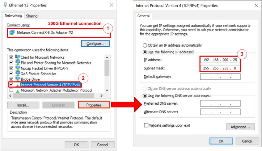
Figure 1 Setting IP Address of the NIC on PC
1) Open Local Area Connection Properties of the 200G Ethernet connection, as shown in the left window of Figure 1.
2) Select “TCP/IPv4” and click on Properties.
3) Set the IP address = 192.168.200.25 and the Subnet mask = 255.255.255.0, as illustrated in the right window of Figure 1.
2.2 Enabling Jumbo Frame of the NIC
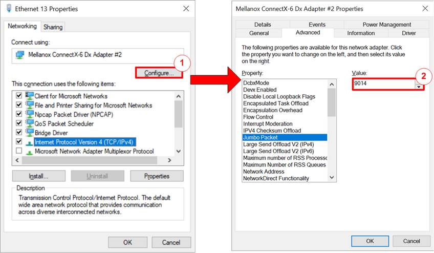
Figure 2 Jumbo Frame Setting
1) On Local Area Connection Properties window, click on “Configure”, as shown in the left windows of Figure 2.
2) On Advanced Tab, select “Jumbo Packet” and set Value to “9014 Bytes” for Jumbo Frame support, as shown in the right windows of Figure 2.
Note: Setting
“Disabled” to disabling Jumbo frame may reduce the performance, so it is
advisable to enable it.
2.3 Disabling Flow Control and Interrupt Moderation
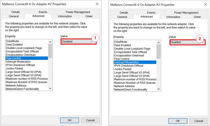
Figure 3 Disable Flow Control and Interrupt Moderation
1) Select “Flow Control” and set the value to “Disabled”, as shown in the left window of Figure 3.
2) Select “Interrupt Moderation” and set the value to “Disabled”, as shown in the right window of Figure 3.
2.4 Power Option Setting
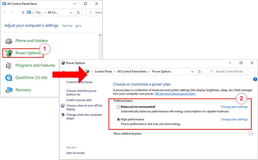
Figure 4 Power Options
1) Open Control Panel and select Power Options, as shown in the left window of Figure 4.
2) Change setting to High Performance, as shown in the right window of Figure 4.
3 Test Menu on FPGA Console
3.1 Display TCPIP Parameters
Choose option ‘0’ to display the current TCP/IP parameters. The console will show the configuration details of the TOE200GADV-IP demo, including local host parameters, TOE#0 (TOE200GADV-IP#0) parameters, and TOE#1 (TOE200GADV-IP#1) parameters, as illustrated in Figure 5. Descriptions for each group are provided below.
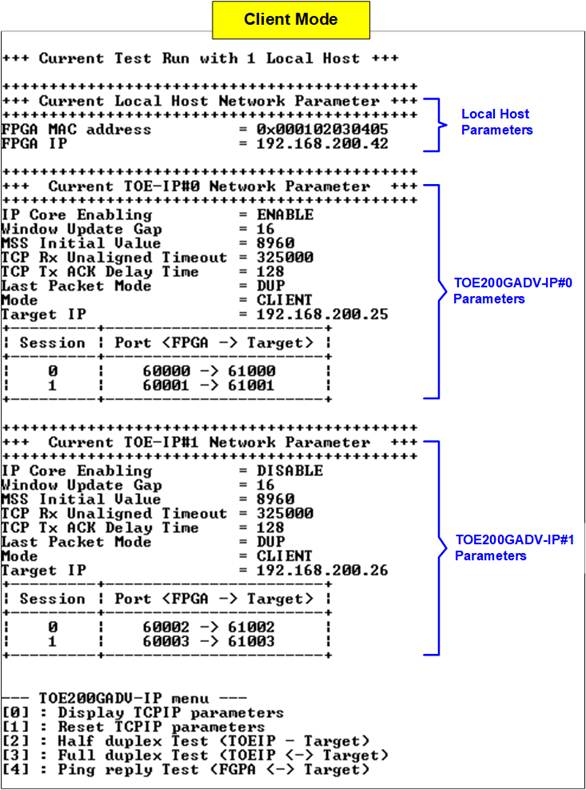
Figure 5 Display Current Parameter Result (Client)
Local Host Parameters
As default, both TOE200GADV-IP instances share the same local host parameters - MAC address and IP address – as described below:
1) FPGA MAC address: Specifies the 48-bit hexadecimal value used as the MAC address of the FPGA. The default value is 0x000102030405.
2) FPGA IP: Defines the IP address of the FPGA. The default value is 192.168.200.42.
Note: This value is used as the Server IP address by the test
application on the PC-based target.
TOE-IP Parameters
This section displays the remaining configuration parameters of each TOE200GADV-IP instance (TOE#0 or TOE#1), including ten parameters in Client/Server mode or eleven parameters in Fixed-MAC mode. Default values depend on the selected initialization mode, as shown in Figure 5 and Figure 6.
1) IP Core Enabling: Enables or disables the selected TOE-IP instance. If disabled, the instance remains in reset until re-enabled by the user. By default, TOE#0 is enabled and TOE#1 is disabled.
2) Window Update Gap: Specifies the threshold (in 1 KB units) for transmitting a Window update packet. The default value is 16.
3) MSS Initial Value: Sets the initial Maximum Segment Size (MSS) used for TCP connection negotiation with the target device. The default value is 8960.
4) TCP Rx Unalign Timeout: Defines the timeout (in clock cycles) for flushing unaligned (non-1024-bit) received data held inside the IP. The default is 1 msec.
Note: In the setup shown in Figure 5, the user clock frequency is 325 MHz, so the timeout is set to 325,000 clock cycles.
5) TCP Tx ACK Delay: Sets the delay (in clock cycles) before TOE200GADV-IP sends an ACK packet. Default is 128 cycles.
6) Last Packet Mode: Specifies the behavior of the final data packet (e.g., duplicated packet, PSH-flagged, or normal). The default setting is DUP (duplicated packet).
7) Mode: Sets the initialization mode to Client, Server, or Fixed-MAC. The default is Client.
Note: Use Client mode if the host FPGA and target PC are on the same network. If they are on different networkds, use Fixed-MAC mode, and set the target MAC address to match the gateway’s MAC address on the FPGA side.
8) Target MAC address (Fixed-MAC mode only): Sets the 48-bit hexadecimal MAC address of the target device. Default value depends on TOE instance:
· TOE#0: 0x554433221100
· TOE#1: 0x504030201000
9) Target IP: Defines the IP address of the target device. The default value depends on the initialization mode:
· Client/Fixed-MAC: TOE#0 = 192.168.200.25, TOE#1 = 192.168.200.26
· Server: Both TOE#0 and TOE#1 = 192.168.200.42
10) Two FPGA Port Numbers (FPGA -> Target): Sets the local port numbers for two TCP sessions. Default value depends on the initialization mode.
· Client/Fixed-MAC:
· TOE#0 = 60000 (Session#0) and 60001 (Session#1)
· TOE#1 = 60002 (Session#0) and 60003 (Session#1)
· Server:
· TOE#0 = 61000 (Session#0) and 61001 (Session#1)
· TOE#1 = 61002 (Session#0) and 61003 (Session#1)
11) Two Target Port Numbers (FPGA -> Target): Sets the target port numbers used for TCP payload transfer. Default value depends on the initialization mode.
· Client/Fixed-MAC:
· TOE#0 = 61000 (Session#0) and 61001 (Session#1)
· TOE#1 = 61002 (Session#0) and 61003 (Session#1)
· Server:
· TOE#0 = 60000 (Session#0) and 60001 (Session#1)
· TOE#1 = 60002 (Session#0) and 60003 (Session#1)
To modify any of these parameters, select menu option [1] Reset TCPIP Parameters.
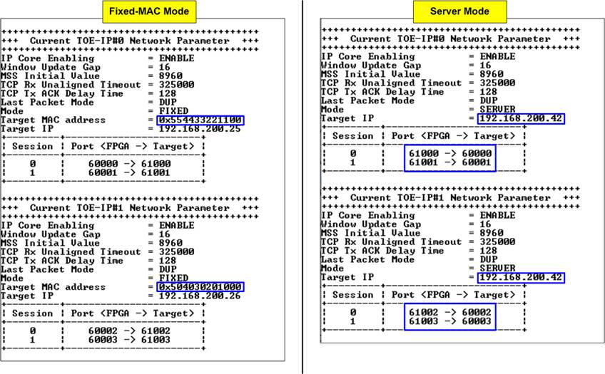
Figure 6 Display Current Parameter Result of Fixed-MAC and Server Mode
3.2 Reset TCPIP Parameter
Choose option ‘1’ from the menu to reset both TOE200GADV-IP (TOE-IP) instances and modify their parameters. This menu allows user to update TOE-IP configurations or keep a TOE-IP instance in a reset state. The parameters are divided into three categories: Local Host (shared between both TOE-IP instances), TOE-IP#0, and TOE-IP#1.
The current parameters of each group are displayed individually. The user can either confirm the use of existing values by entering ‘x’ or choose to modify them by pressing any other key. After the parameters of each TOE-IP instance are confirmed, the corresponding IP is reset and begins its initialization process.
All user inputs are validated before being applied. If an input is invalid, the corresponding parameter will remain unchanged. For descriptions of each parameter, refer to Section 3.1 (Display TCPIP Parameters). The valid ranges for each parameter are detailed below.
Figure 7 shows Local Host Parameters settings, which appear as the first section when entering the “Reset TCPIP Parameter” menu. It also illustrates an example of modifying the IP Address of the local host.
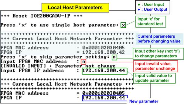
Figure 7 Change Local Host Parameters of FPGA
Local Host Parameters
1) FPGA MAC address: Input 12-digits hexadecimal value with the prefix “0x”.
2) FPGA IP: Input four decimal numbers separated by “.”. Each value must be in the range of 0-255.
Following the local host parameter
settings, the menu proceeds to update TOE#0, followed by TOE#1. Each TOE-IP instance
contains eleven configurable parameters, described below:
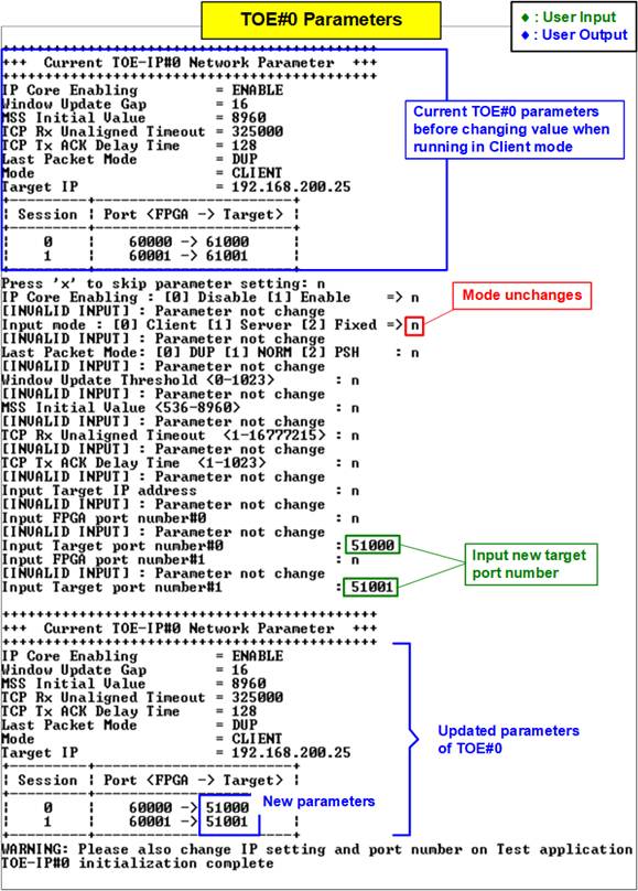
Figure 8 Change TOE-IP Parameter Using Same Initialization Mode
TOE-IP Parameters
1) IP Core Enabling: Input ‘0’ for disable or ‘1’ for enable the TOE-IP.
2) Window Update Gap: Sets the threshold for transmitting a Window update packet. The valid range is 0x000 – 0x3FF (0-1023), with a unit size of 1KB.
3) MSS Initial Value: Sets the initial MSS in bytes for TCP negotiation. The valid range is 536 – 8960.
4) TCP Rx Unalign Timeout: Sets the timeout (in clock cycles) to flush unaligned received data. The valid range is 0x000000 – 0xFFFFFF (0-16,777,215).
5) TCP Tx ACK Delay: Sets the delay (in clock cycles) before sending an ACK. The valid range is 0x000 – 0x3FF (0-1023).
6) Last Packet Mode: Input ‘0’, ‘1’, or ‘2’ to configure TOE-IP to send a duplicated last packet, a last packet with the PSH flag, or a normal packet. The default value is ‘0’ (duplicated last packet).
7) Mode: Input ‘0’, ‘1’, or ‘2’ to set the initialization mode to Client, Server, or Fixed-MAC, respectively.
Note: The mode must be selected based on how the MAC address of the target device will be obtained.
8) Target MAC address (Fixed-MAC mode only): Input 12-digit hexadecimal value with the prefix “0x”.
9) Target IP: Input four decimal values separated by “.”, where each value is 0-255.
10) FPGA port numbers: Input a value within the range of 0 to 65535.
Note: Each session must use a unique port number.
11) Target port numbers: Input a value within the range of 0 to 65535.
Figure 8 shows an example of modifying the target port number while keeping the initialization mode unchanged. After parameter configuration is complete, TOE#0 beings its initialization with the target device. When finished, the message “TOE#0 initialization complete” appear on the console.
When updating TOE-IP parameters, if the user changes the initialization mode, the default parameters of the newly selected mode are displayed automatically, as shown in Figure 9. For example, if the mode is changed from Client to Server, the console will display the default Server mode parameters.
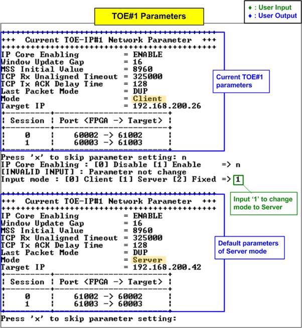
Figure 9 New Default Parameters After Changing Initialization Mode
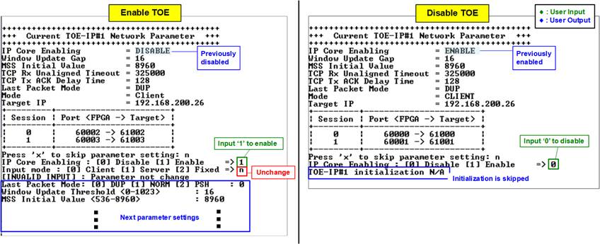
Figure 10 Change Enabling of TOE-IP
The left window of Figure 10 shows an example where TOE#1 is changed from disabled to enabled. If the initialization mode remains unchanged, the console proceeds to the next parameter settings.
The right window shows TOE#1 being changed from enabled to disabled. When a TOE-IP instance is disabled, the subsequent parameter settings and initialization process for TOE-IP#1 are skipped.
3.3 Half-Duplex Test
Choose option ‘2’ from the menu to initiate a one-way data transfer for each session of the TOE-IP. If the target system is PC, the test application, ‘tcpdatatest.exe’, should be executed from the command prompt with the appropriate parameters for sending or receiving data. The half-duplex test allows each session to be configured independently with one of three options: disable (option ‘0’), send data (option ‘1’), or receive data (option ‘2’). Users can also assign distinct test parameters to each session. The following sections explain the operation of the host FPGA during Send or Receive tests with a target device, which may be either PC-based or FPGA-based.
3.3.1 Send Test with PC-Based Target
When the test mode is set to ‘1-Send test’ on the FPGA, the PC must run the “tcpdatatest” application to receive data. Ensure the PC uses the recommended parameters for each session. The sequence for the Send test is outlined as follows.
1) On the FPGA console, input each session with the following test parameters:
· Test mode: ‘0’ - Disable the session or ‘1’ - Send test.
· Transfer size: The number of bytes to transmit. The valid range is 0x1 – 0xFFFF_FFFF_FFFF. Use decimal format by default or prefix with “0x” for hexadecimal.
· Packet size: The packet size in bytes using the same input rules and range as Transfer size.
· User TxPacket gap size: The pause duration (in clock cycles) after sending each packet. The valid range is 0 – 255.
· Max speed: Input a value between 1-100 to be a percentage of total user logic bandwidth (41,600 MB/s for 325 MHz UserClk or 42,624 MHz for 333 MHz UserClk).
· Mode: FPGA connection mode. Input ‘1’ to initiate passive open (Server mode) when the PC runs ‘tcpdatatest’ as the Client.
Repeat this step for all sessions.
2) Upon validation of all inputs, the FPGA console displays the recommended parameters for running the test application on the PC. Next, the active session parameters are shown, followed by a “Wait connection” message, prompting the user to launch the PC-side application.
3) On the PC Command prompt, run “tcpdatatest” using the recommended values provided by the FPGA console. The last two parameters (‘pattern’ and ‘buffer’) may be adjusted for performance evaluation. The command requires seven parameters, as shown below:
>> tcpdatatest <mode> <dir> <server IP> <server port> <bytelen> <pattern><buffer>
· Mode: Input ‘c’ to configure PC to operate as a Client.
· Dir: Input ‘r’ to receive and verify incoming data.
· Server IP: Input the local host (FPGA) IP address.
· Server port: Input the local host (FPGA) port number on the selected session.
· Bytelen: Input the same value as ‘Transfer size’ from step 1) on the selected session.
· Pattern: Input ‘1’ to enable data verification or ‘0’ to skip it.
· Buffer: Input a value between 1-5 (64KB to 1MB buffer size for the application).
4) After launching the test application, the connection is established. Once all active sessions are connected, the FPGA console displays three target parameters: the port number, Maximum Segment Size (MSS), and Window scaling factor. The data transfer progress is then updated every second - transmit progress appears on the FPGA console, while received data is shown on the PC Command prompt. When a session completes its transmission, the status “Closed” is displayed on the console.
Note: The port number shown on the PC may differ from the assigned target parameter on the FPGA console due to OS-level allocation.
5) After all connections are closed, the FPGA console displays “Half-duplex test complete”, followed by hardware statistics and performance results. The Command prompt also displays receive performance.
One-Session Test with PC-Based Target
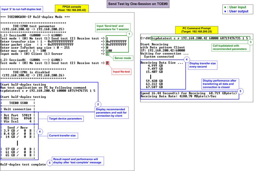
Figure 11 One-Session Send Test with PC-Based Target
Figure 11 illustrates a one-session Send test from TOE#0 to a PC-based target. The left window shows the FPGA console operating in Server mode, while the right window shows the PC Command prompt running in Client mode. Data verification is enabled on the PC test application.
To demonstrate peak performance, both the packet size and transfer size are set to 68 GB, with zero packet gap size and the maximum speed set to 100%. When data verification is enabled, the receive performance achieved on the PC is 4180 MB/s.
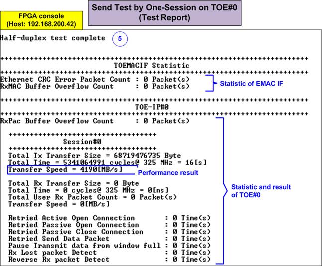
Figure 12 Statistic and Result on FPGA Console Upon Test Complete
Once the test is complete, the FPGA console displays statistics and test results, divided into several sections: TOEMACIF, TOE#0 (if active), and TOE#1 (if active). In this test, TOE#1 is disabled, so no report is shown for it.
As shown in Figure 12, the TOEMACIF Statistics section includes:
· CRC Error Packet Count: Number of Ethernet packets that the Ethernet MAC detected with CRC error.
· RxMAC Buffer Overflow Count: Number of Ethernet packets discarded due to buffer overflow in the TOEMACIF.
Each active TOE-IP instance displays:
· Common Report (shared across sessions):
· RxPac Buffer Overflow Count: Shows the number of discarded packets due to internal buffer overflow in the TOE-IP.
· Session Report (for each active session):
· Transmit Report: Displays the total transmitted data size, total time used, and transmit performance.
· Receive Report: Displays the total received data size, total time used, and receive performance.
· Retried Count: Shows the number of retry event triggered by interrupt statuses, indicating packet loss detected by TOE-IP during corresponding operation.
Note: In this test, a short optical cable is used for direct connection between the host and target, so no errors or retries are reported. Retry counts may appear when using different cables or in more complex test environments.
Two TOE-IPs Enabled with Two PC-Based Targets
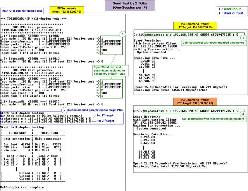
Figure 13 Two TOE-IPs Send Test with Two PC-Based Targets
Figure 13 demonstrates a test setup where two TOE200GADV-IP instances (TOE-IP#0 and TOE-IP#1) are enabled, each transmitting data to a separate PC-based target using one session per TOE-IP. To allow a direct comparison with the previous one-session test, both TOE-IPs use the same configurations: transfer size, packet size, packet gap size, and maximum speed. TOE-IP#0 is configured to communicate with a target at IP address 192.168.200.25, while TOE-IP#1 communicates with a second target at IP address 192.168.200.26.
Since both TOE-IPs share the same Ethernet MAC interface, bandwidth contention may lead to performance differences when transmitting data to two PC targets simultaneously. As shown in Figure 13, TOE#1 exhibits reduced performance while both sessions are active. Once TOE-IP#0 completes its transmission and only TOE-IP#1 remains active, its performance improves. The final results on the PC command prompt show that the first target achieved a receive performance of 4350 MB/s, while the second target reached 3177 MB/s.
Compared to a single-session setup, using two sessions improves the total throughput by approximately 70%, although this value may vary depending on system conditions, particularly the target PC’s operating system behavior.
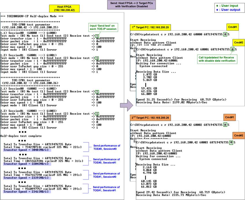
Figure 14 All Session Send Performance with Disable Data Verification on PC-Based Target
When the total number of TCP sessions is increased to four (two sessions per TOE-IP), the performance of each individual session decreases. To reduce CPU workload, data verification in the test application on the PC-based target can be disabled. As shown in Figure 14, this results in a slight improvement in total transfer performance. Since the application is built using standard system libraries, its efficiency is largely dependent on the operating system’s resource management.
Max Speed Limit
In certain applications, multiple TCP sessions are used to transfer various data types, each requiring a specific data rate. This demo allows users to configure the maximum transfer speed for each TCP session individually, specified as a percentage of the maximum bandwidth. The maximum bandwidth is determined by the formula: “User clock frequency x 1024-bit data width”. For example, with a 325 MHz user clock, the theoretical peak speed is 41,600 MB/s.
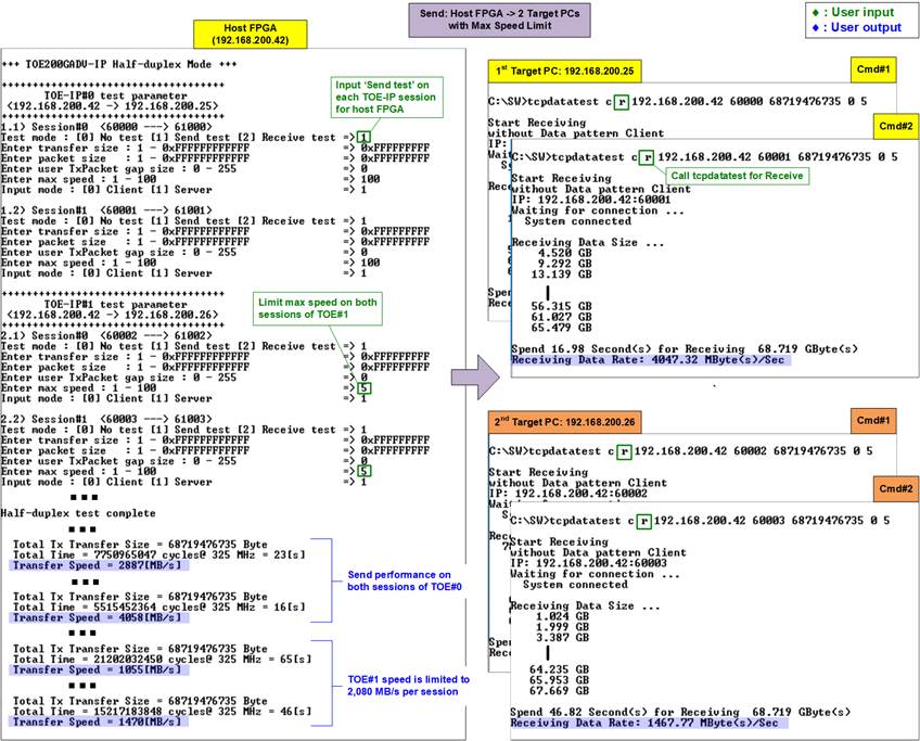
Figure 15 Send Performance with Max Speed Limit on Some TCP sessions
Figure 15 demonstrates a scenario where the maximum speed for both sessions of TOE#1 on the FPGA-based host is restricted, while TOE#0 operates without a speed limit. As a result, each TCP session performance on TOE#1 is capped at 2,080 MB/s, which is 5% of 41,600 MB/s.
Other parameters also influence test performance such as the initial MSS value, Window update gap, various timeout settings, small packet size, and the interval between packet transmissions (TxPacket Gap). Detailed descriptions of these parameters can be found in the TOE200GADV-IP datasheet and reference design document.
Error Messages on FPGA Console
If the user enters invalid values for required test parameters – such as test mode, transfer size, or packet size – the FPGA console displays an error message like “OUT-OF-RANGE INPUT” or “INVALID INPUT”, as shown in Figure 16. Since no default values are defined for these parameters, valid input is required.
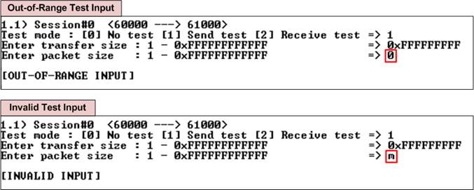
Figure 16 Test Input Invalid
3.3.2 Receive Test with PC-Based Target
When the test mode is set to ‘2-Receive test’ on the FPGA, the PC must run the “tcpdatatest” application to send data. Ensure the PC uses the recommended parameters for each session. The following outlines the Receive test procedure.
1) On the FPGA console, input each session with the following test parameters:
· Test mode: ‘0’ - Disable the session or ‘2’ - Receive test.
· Transfer size: The number of bytes to receive. The valid range is 0x1 – 0xFFFF_FFFF_FFFF. Use decimal format by default or prefix with “0x” for hexadecimal.
· Data verification: ‘0’ - Disable data verification or ‘1’ - Enable data verification.
· Max speed: Input a value between 1-100 to be a percentage of total user logic bandwidth (41,600 MB/s for 325 MHz UserClk or 42,624 MHz for 333 MHz UserClk).
· Mode: FPGA connection mode. Input ‘1’ to initiate passive open (Server mode) when the PC runs ‘tcpdatatest’ as the Client.
Repeat this step for all sessions.
2) This step matches step 2) in Section 3.3.1 (Send Test with PC-Based Target). After parameter validation, the console waits for the incoming connection.
3) On the PC Command prompt, run “tcpdatatest” using the recommended values provided by the FPGA console. The last two parameters (‘pattern’ and ‘buffer’) may be adjusted for performance evaluation. The command requires seven parameters, as shown below:
>> tcpdatatest <mode> <dir> <server IP> <server port> <bytelen> <pattern><buffer>
· Mode: Input ‘c’ to configure PC to operate as a Client.
· Dir: Input ‘t’ to send data.
· Server IP: Input the local host (FPGA) IP address.
· Server port: Input the local host (FPGA) port number on the selected session.
· Bytelen: Input the same value as ‘Transfer size’ from step 1) on the selected session.
· Pattern: ‘0’ – Dummy data or ‘1’ - Incremental data for test pattern, matching the value of “Data verification” from step 1) on the selected session.
· Buffer: Input a value between 1-5 (64KB to 1MB buffer size for the application).
4) The transfer status and completion message follow the same behavior as steps 4) – 5) in Section 3.3.1 (Send Test with PC-Based Target), with the direction reversed. The FPGA console displays receive progress, while the PC Command prompt shows the transmit progress.
One-Session Test with PC-Based Target
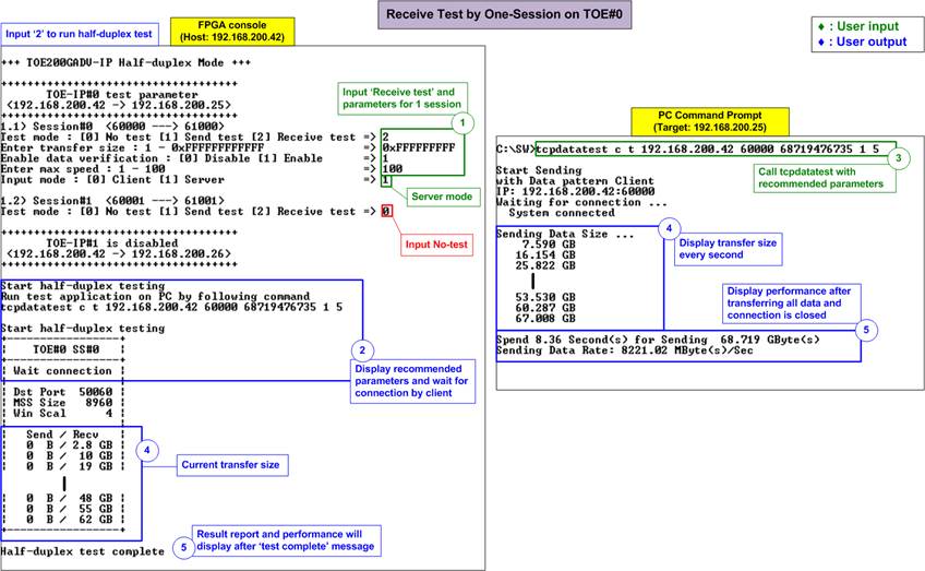
Figure 17 One-Session Receive Test with PC-Based Target
Figure 17 illustrates a one-session Receive test from TOE#0 to a PC-based target. The left window shows the FPGA console operating in Server mode, while the right window displays the PC Command prompt running in Client mode. Data generation is enabled in the PC test application.
In this test, the PC application generates actual data using an incremental pattern generator, while the FPGA performs data verification. Despite using only a single session, the transmit performance observed on the PC command prompt reaches 8221 MB/s – nearly double the performance typically achieved during a single-session Send test using a PC-based target.
Mixed Send and Receive Test with PC-Based Target
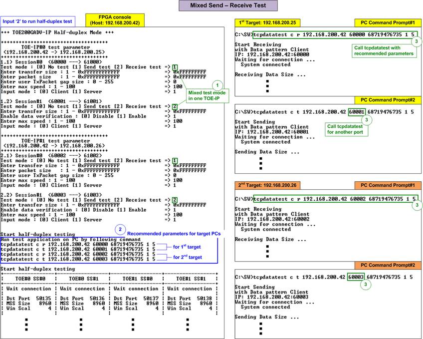
Figure 18 Mixed Send and Receive Test with PC-Based Target
Each TOE-IP and its session operation independently, allowing users to run mixed Send and Receive tests within the same TOE-IP. Figure 18 demonstrates an example where all four sessions are enabled, with a mix of Send and Receive operations assigned to each TOE-IP.
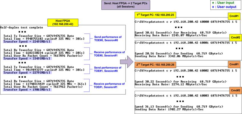
Figure 19 Performance Result of Mixed Send-Receive Test with PC-Based Target
After all sessions complete their transfer, the performance results for each session are displayed separately, as shown in Figure 19. Due to limitations in PC resource, the total performance across four sessions does not reach the full 200G Ethernet full bandwidth.
It’s important to note that each TCP session inherently supports full-duplex data transfer, meaning two sessions are not required to achieve bidirectional communication. An example of full-duplex operation is discussed in Section 3.4 (Full-Duplex Test).
3.3.3 Test with FPGA-Based Target
To perform unidirectional data transfer between an FPGA-based host and an FPGA-based target, choose option ‘2’ on both FPGA consoles – one configured for the Send test and the other for the Receive test. The following sequences outlines how to initiate a Send test from the host and a Receive test on the target.
Note: The “mode” setting in the half-duplex test defines only the method of connection establishment: the Client initiates the connection, while the Server waits for it. The connection termination behavior is determined by the test modes: the sender (Send test) is assigned the role of active closer (Client), and the receiver (Receive test) performs passive close (Server). Although the connection mode options - Client (active mode) and Server (passive mode) – are named similarly to the TOE-IP initialization modes, they are configured separately and serve different purposes.
1) On the host FPGA console (configured for Send test in Server mode), input each session with the following test parameters:
· Test mode: ‘0’-Disable the session or ‘1’-Send test.
· Transfer size: The number of bytes to transmit. The valid range is 0x1 – 0xFFFF_FFFF_FFFF. Use decimal format by default or prefix with “0x” for hexadecimal.
· Packet size: The packet size in bytes using the same input rules and range as Transfer size.
· User TxPacket gap size: The pause duration (in clock cycles) after sending each packet. The valid range is 0 – 255.
· Max speed: Input a value between 1-100 to be a percentage of total user logic bandwidth (41,600 MB/s for 325 MHz UserClk or 42,624 MHz for 333 MHz UserClk).
· Mode: FPGA connection mode. Input ‘1’ to enable passive open (Server mode).
Repeat this step for all sessions.
2) Upon validation of all inputs, the FPGA console displays the recommended parameters (originally intended for PC applications), followed by the active session parameters and a “Wait connection” message, indicating readiness to accept incoming connections.
3) On target FPGA console (configured for Receive test in Client mode), input each session with the following test parameters:
· Test mode: ‘0’-Disable the session or ‘2’-Receive test.
· Transfer size: Input the same value as step 1) to specify the number of bytes to receive.
· Data verification: Set to ‘1’ to enable data verification, as the data transmitted from the FPGA is always incremental pattern data, not dummy data.
· Max speed: Input a value between 1-100 to be a percentage of total user logic bandwidth (41,600 MB/s for 325 MHz UserClk or 42,624 MHz for 333 MHz UserClk).
· Mode: FPGA connection mode. Input ‘1’ to initiate active open (Client mode).
Repeat this step for all sessions.
4) Upon validation of all inputs, the FPGA console displays the active session parameters and prompts with “Press any key to proceed”. Pressing a key triggers connection establishment.
5) Once all active connections are established, the console displays three target parameters: the port number, Maximum Segment Size (MSS), and Window scaling factor. Transfer progress updates every second - receive progress on the host console, and transmit progress on the target console. When a session completes its transmission, the message “Closed” appears.
6) After all sessions complete and connection closes, the message “Half-duplex test complete” is displayed, followed by hardware statistics and performance results.
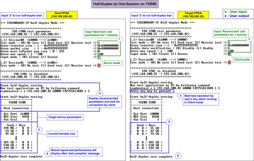
Figure 20 One-Session Half-Duplex Transfer with FPGA-Based Target
Figure 20 illustrates an example of a one-session Send test from TOE#0 on the host FPGA to the TOE#0 on target FPGA (a separate FPGA board). The left window represents the Send test console on the host running in Server mode, while the right window shows the Receive test console on the target running in Client mode. In this example, the host and a target are connected directly, achieving consistent full 200G Ethernet performance throughout the test.
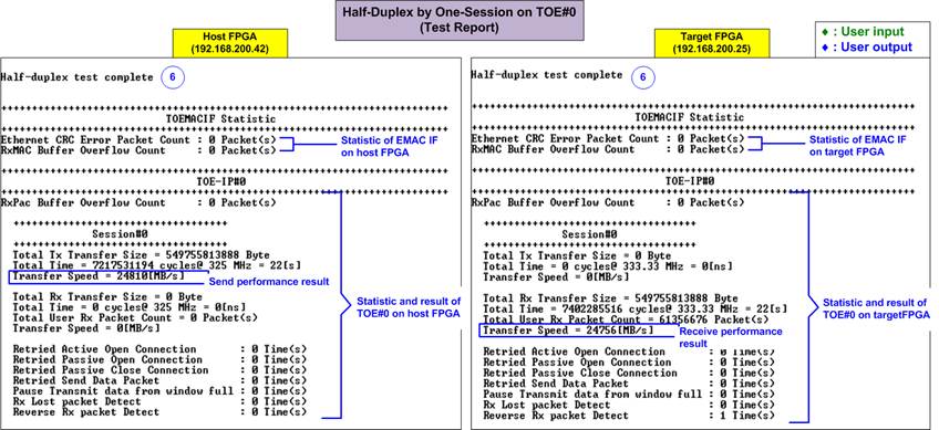
Figure 21 Statistic and Result on FPGA Consoles Upon Test Complete
Upon completion, test reports are displayed on both FPGA consoles, as illustrated in Figure 21. The left window presents the result from the host FPGA, while the right window shows the result from the target FPGA. No errors or retry counts are reported when using a direct connection with a short-length optical cable. However, using different hardware or network conditions may result in non-zero error or retry counts.
Note: Figure 21 displays results where the host and target use different FPGA configuration files. The host FPGA runs a design with a user clock frequency of 325 MHz, while the target FPGA operates with a 333 MHz user clock frequency.
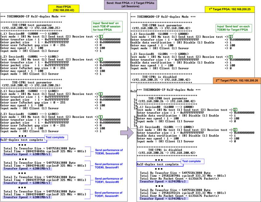
Figure 22 All Session Half-Duplex Performance with FPGA-Based Target System
Figure 22 illustrates a test where all four sessions are enabled using an FPGA-based target. On the host FPGA, all sessions are configured for Send tests, while the target FPGA runs corresponding Receive tests. Similar to the single-session test with an FPGA-based target, the total throughput reaches the full 200G Ethernet bandwidth. Additionally, each session achieves nearly identical performance, demonstrating effective load balancing. This contrasts with the imbalanced results seen in the two TOE-IP Send Test with PC-based targets shown in Figure 13.
3.4 Full-Duplex Test
Choose option ‘3’ from the FPGA console menu to perform a full-duplex test. This test enables simultaneous data transfer in both directions for each TCP session. When using a PC-based target system, the PC runs the “tcp_client_txrx_single” application from the Command prompt. Before initiating the test, ensure that the number of active TCP session is the same on both the host and target systems. The detailed steps for running full-duplex test between the host and target systems are elaborated below.
3.4.1 Test with PC-Based Target
Once all TCP session parameters are configured, the host FPGA console will display the recommended settings for running the ‘tcp_client_txrx_single’ application on a PC-based target system. The following sequence outline how to run the test when the FPGA-based host system is configured in Server mode while the PC-based target operates in Client mode.
1) On the FPGA console, input each session with the following test parameters.
· Test mode: ‘0’ - Disable the session or ‘1’ – Full-duplex test.
· Transfer size: The number of bytes to transfer. The valid range is 0x1 – 0xFFFF_FFFF_FFFF. Use decimal format by default or prefix with “0x” for hexadecimal.
· Packet size: The packet size in bytes using the same input rules and range as Transfer size.
· User TxPacket gap size: The pause duration (in clock cycles) after sending each packet. The valid range is 0 – 255.
· Data verification: ‘0’ - Disable data verification or ‘1’ - Enable data verification.
· Max speed: Input a value between 1-100 to be a percentage of total user logic bandwidth (41,600 MB/s for 325 MHz UserClk or 42,624 MHz for 333 MHz UserClk).
· Mode: FPGA connection mode. Input ‘1’ to initiate passive open and close (Server mode).
Repeat this step for all sessions.
2) Upon validation of all inputs, the FPGA console displays the recommended parameters for running the test application on the PC. Next, the active session parameters are shown, followed by a “Wait connection” message, prompting the user to launch the PC-side application.
3) On the PC Command prompt, run “tcp_client_txrx_single” using the recommended values provided by the FPGA console. The last two parameters (‘pattern’ and ‘buffer’) may be adjusted for performance evaluation. The command requires five parameters, as shown below:
>> tcp_client_txrx_single <server IP> <server port> <bytelen> <pattern><buffer>
· Server IP: Input the local host (FPGA) IP address.
· Server port: Input the local host (FPGA) port number on the selected session.
· Bytelen: Input the same value as ‘Transfer size’ from step 1) on the selected session.
· Pattern: ‘0’ - Send dummy data, ‘1’ - Send incremental data, matching the value of “Data verification” from step 1) on the selected session.
· Buffer: Input a value between 1-5 (64KB to 1MB buffer size for the application).
4) After launching the test application, the connection is established. Once all active sessions are connected, the FPGA console displays three target parameters: the port number, Maximum Segment Size (MSS), and Window scaling factor. The data transfer progress in both directions is then updated every second on both the FPGA console and the PC Command prompt. A “Closed” message appears once each session completes.
Note: The port number shown on the PC may differ from the assigned target parameter on the FPGA console due to OS-level allocation.
5) After all connections are closed, the FPGA console displays “Full-duplex test complete”, followed by hardware statistics and performance results. The Command prompt also displays transfer performance in both directions.
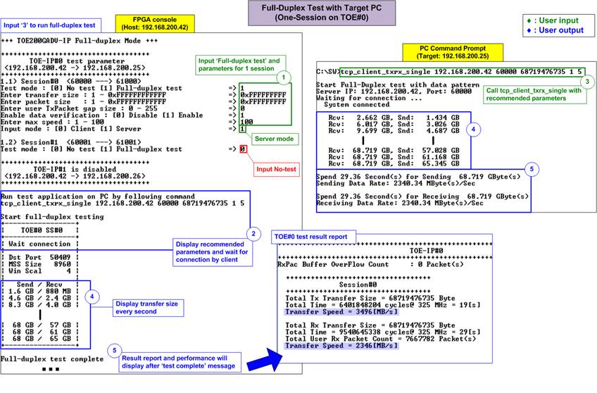
Figure 23 One-Session Full-Duplex Test with PC-Based Target
Figure 23 demonstrates the configuration steps for a one-session full-duplex test. The left window displays the FPGA console, while the right window shows the PC Command prompt. When using a PC-based target, full-duplex transfer consumes more PC resources compared to half-duplex transfer. As a result, the performance of a one-session full-duplex test with a PC-based target is lower than that of a one-session half-duplex test. In contrast, when using an FPGA-based target, the full-duplex test achieves the same performance as the half-duplex test. Further details are discussed in the next section.
Note: The “tcp_client_txrx_single” application uses a single timer to measure both transmission and reception durations. Therefore, the transmit and receive performance displayed on the PC Command prompt are equal.
3.4.2 Test with FPGA-Based Target
To perform a full-duplex test between an FPGA-based host and an FPGA-based target, choose option ‘3’ from the FPGA console menu on both systems. This test allows user to configure parameters for each TCP session independently via the console. The following sequence provides an example where the host operates in Server mode, and the target FPGA operates in Client mode.
Note: The “mode” setting in the full-duplex test defines only the method of connection establishment and termination: the Client initiates and terminates the connection, while the Server waits for it. Although the connection mode options - Client (active mode) and Server (passive mode) – are named similarly to the TOE-IP initialization modes, they are configured separately and serve different purposes.
1) On the host FPGA console (configured in Server mode), input each session with the following test parameters.
· Test mode: ‘0’ - Disable the session, ‘1’ - Full-duplex test.
· Transfer size: The number of bytes to transfer. The valid range is 0x1 – 0xFFFF_FFFF_FFFF. Use decimal format by default or prefix with “0x” for hexadecimal.
· Packet size: The packet size in bytes using the same input rules and range as Transfer size.
· User TxPacket gap size: The pause duration (in clock cycles) after sending each packet. The valid range is 0 – 255.
· Data verification: Set to ‘1’ to enable data verification, as the data transmitted from the FPGA is always incremental pattern data, not dummy data.
· Max speed: Input a value between 1-100 to be a percentage of total user logic bandwidth (41,600 MB/s for 325 MHz UserClk or 42,624 MHz for 333 MHz UserClk).
· Mode: FPGA connection mode. Input ‘1’ to initiate passive open and close (Server mode).
Repeat this step for all sessions.
2) Upon validation of all inputs, the FPGA console displays the recommended parameters (originally intended for PC applications), followed by the active session parameters and a “Wait connection” message, indicating readiness to accept incoming connections.
3) On the target FPGA console (configured in Client mode), input each session with the following test parameters.
· Test mode: ‘0’ - Disable the session, ‘1’ - Full-duplex test.
· Transfer size: Input the same value as step 1) to specify the transfer size on the selected session.
· Packet size: The packet size in bytes using the same input rules and range as Transfer size.
· User TxPacket gap size: The pause duration (in clock cycles) after sending each packet. The valid range is 0 – 255.
· Data verification: Set to ‘1’ to enable data verification, as the data transmitted from the FPGA is always incremental pattern data, not dummy data.
· Max speed: Input a value between 1-100 to be a percentage of total user logic bandwidth (41,600 MB/s for 325 MHz UserClk or 42,624 MHz for 333 MHz UserClk).
· Mode: FPGA connection mode. Input ‘0’ to initiate active open and close (Client mode).
Repeat this step for all sessions.
4) Upon validation of all inputs, the FPGA console displays the active session parameters and prompts with “Press any key to proceed”. Pressing a key triggers connection establishment.
5) Once all active connections are established, the console displays three target parameters: the port number, Maximum Segment Size (MSS), and Window scaling factor. Transfer progress updates every second on both the host and target consoles. When a session completes its transmission, the message “Closed” appears.
6) After all sessions complete and connection closes, the message “Full-duplex test complete” is displayed, followed by hardware statistics and performance results on both consoles.
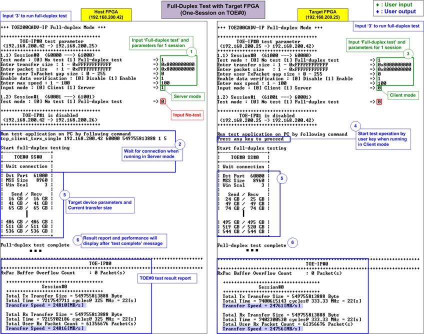
Figure 24 One-Session Full-Duplex Test with FPGA-Based Target
Figure 24 demonstrates the configuration steps for a one-session full-duplex test using an FPGA-based target. The left window shows the host console, while the right window displays the target console. With an FPGA-based target, the full-duplex test using a single session achieves consistent line-rate throughput. Both the host and target are able to transmit data to each other within a single session at approximately 24,800 MB/s, matching the performance observed in the half-duplex test with an FPGA-based target.
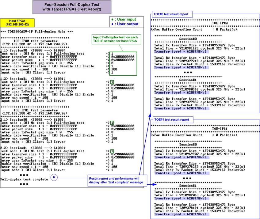
Figure 25 Test Result of Four-Session Full-Duplex Test with FPGA-Based Target
When using FPGA-based target, a four-session full-duplex transfer can achieve the full bandwidth of 200G Ethernet, with balanced performance across all sessions. Each session delivers approximately 6200 MB/s, resulting in a total throughput of 24,800 MB/s. This allows systems handling multiple data types to assign each type to a separate session without compromising overall system performance.
3.5 Ping Test
The TOE200GADV-IP demo also includes support for low-speed connections, which are handled by the CPU firmware and do not require high-throughput operation. As a demonstration of this feature, the system supports the standard Ping command: when a Ping request is received from a PC-based target, the system responds with a Ping reply. To initiate the test, select option ‘4’ from the host console menu.
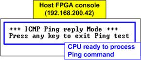
Figure 26 Ping Reply Mode Result on Host Console
Upon selecting this option, the console will display the message “Press any key to exit Ping test”, as illustrated in Figure 26. After that, users can enter the command “ping <IP address of the host system>” in the PC Command prompt to begin the Ping command test, as shown in Figure 27.
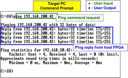
Figure 27 Ping Command Result on PC-Based Target
To exit the Ping test, press any key on the host console. This will return the system to the main menu, as shown in Figure 28.
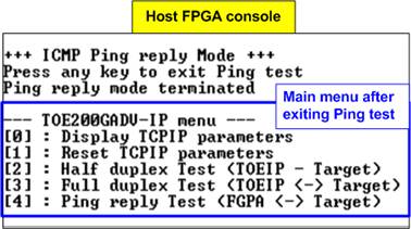
Figure 28 Main Menu is Re-display once Exiting the Ping Test
4 Revision History
|
Revision |
Date (D-M-Y) |
Description |
|
2.00 |
6-May-25 |
Update the demo structure to include 2 TOE200GADV IPs (support 2 targets) |
|
1.00 |
13-Jun-24 |
Initial version release |