WireGuard10G-IP Reference Design
2.4 Ethernet Header Decapsulation Module
2.5 Ethernet Header Encapsulation Module
3.5 Initialize TAI64 Timestamp
3.7 Set WireGuard Interface Address IP
3.13 Show Ephemeral Private Key
1 Introduction
This document describes the reference design details for the WireGuard 10Gbps IP Core (WireGuard10G-IP). This system is engineered to serve as a high-performance communication medium for transferring data through secure tunnels, fully compliant with the WireGuard VPN protocol standard. The design focuses on hardware-level data management to maximize throughput up to 10Gbps, encompassing hardware-accelerated noise handshake protocol execution and authenticated encryption/decryption at line rate.
The operational workflow begins with handling incoming network traffic through the 10GEMAC module, which is then forwarded to the IPv4 Routing module to filter data based on defined security policies. Subsequently, the data enters the decapsulation process to be reorganized and prepared before reaching the WireGuard10G-IP for security processing. Conversely, processed data is encapsulated with appropriate frame headers via the Encapsulation module, ensuring all outgoing packets are correctly formatted according to Ethernet standards for transmission to the remote network.
This architecture enables users to deploy and utilize Virtual Networks via the WireGuard protocol at peak performance without burdening the main processing unit. By completely offloading the Data Plane operations to the FPGA hardware, the host system is relieved from the intensive computational tasks required for complex cryptographic algorithms and high-speed packet management. Consequently, the system maintains consistent throughput and high stability, even when processing massive volumes of continuous data.
Regarding management and control, the design integrates a Processing System as the central controller. Users can interact with the system via a serial console to configure network parameters—such as IP addresses and cryptographic keys for each peer—and monitor real-time hardware status. All configurations are synchronized through high-speed interfaces to internal hardware registers, ensuring seamless and reliable coordination between the control and data planes.
The following sections provide an in-depth look at the hardware architecture, including data path management, clock domain handling, and control firmware design. These details serve as a comprehensive guide for implementing or extending this high-security system on 10Gbps network infrastructures.
2 Hardware Overview
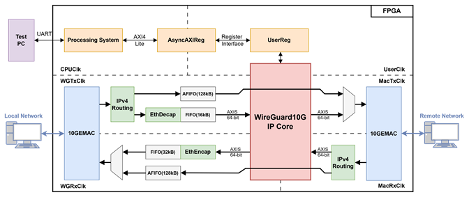
Figure 1 WireGuard10G-IP reference design block diagram
In this reference design, the FPGA functions as a high-speed WireGuard Accelerator, facilitating secure data transfer over a 10GbE network. The hardware architecture utilizes two 10G Ethernet Media Access Controllers (10GEMAC): one interface handles raw data from the local network (User side), while the other manages encrypted tunnel traffic communicating with the remote network.
The system's control plane allows for the configuration of network and WireGuard-specific parameters through the UserReg module operating at UserClk. This register set is interfaced with the Processing System (CPU) via an AsyncAxiReg bridge, which translates AXI4-Lite transactions from the CPUClk domain to the register interface.
For the data plane, the system employs 64-bit AXI Stream (AXIS) interfaces. This 64-bit bus width is specifically chosen to integrate seamlessly with the 10GEMAC modules without requiring additional control logic, as it natively supports the data throughput requirements of 10Gbps.
To enhance operational flexibility, the architecture operates across multiple independent clock domains. The WGTxClk and WGRxClk domains are dedicated to the User Data Path, while the MacTxClk and MacRxClk domains handle communications with the 10GEMAC. This multi-clock domain approach allows each section to operate independently, ensuring stable and precise data synchronization between the internal WireGuard10G IP Core and the external physical interfaces.
The details of each module are described as follows.
2.1 AsyncAxiReg
This module is designed to convert the signal interface of AXI4-Lite to be register interface. Also, it enables two clock domains to communicate.
To write register, RegWrEn is asserted to ‘1’ with the valid signal of RegAddr (Register address in 32-bit unit), RegWrData (write data of the register), and RegWrByteEn (the byte enable of this access: bit[0] is write enable for RegWrData[7:0], bit[1] is used for RegWrData[15:8], …, and bit[3] is used for RegWrData[31:24]).
To read register, AsyncAxiReg asserts RegRdReq=’1’ with the valid value of RegAddr (the register address in 32-bit unit). After that, the module waits until RegRdValid is asserted to ‘1’ to get the read data through RegRdData signal at the same clock.
The address of register interface is shared for both write and read transactions, so user cannot write and read the register at the same time. The timing diagram of the register interface is shown in Figure 2.
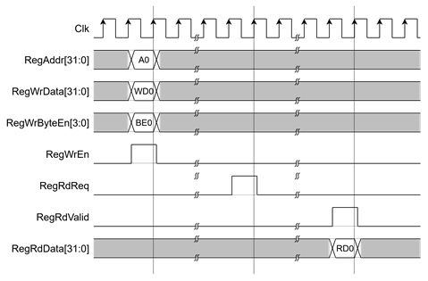
Figure 2 Register interface timing diagram
2.2 UserReg
For register file, UserReg is designed to write/read registers and control of the WireGuard10G-IP corresponding with write register access or read register request from AsyncAxiReg module. The memory map inside UserReg module is shown in Table 1.
Table 1 Register map Definition of WireGuard10G-IP
|
Address Offset |
Register Name |
Description |
|
WireGuard10G Control register |
||
|
|
|
Rd[1:0]: Ethernet link-up status (MacLinkup[1:0]). |
|
|
|
Rd[31:0]: WireGuard Core Version (WGVersion[31:0].) |
|
|
|
Wr[0]: Reset signal active low (rWGRstB). |
|
|
|
Rd[0]: Configuration accepted
status (WGAcceptConfig). |
|
|
|
Wr/Rd[15:0]: Keepalive Timer Settings (rPersistentKeepalive). |
|
|
|
Wr/Rd[31:0]: WG Pre-SharedKey (rPresharedKey[31:0]). |
|
|
|
Wr/Rd[31:0]: WG Pre-SharedKey (rPresharedKey[63:32]). |
|
|
|
Wr/Rd[31:0]: WG Pre-SharedKey (rPresharedKey[95:64]). |
|
|
|
Wr/Rd[31:0]: WG Pre-SharedKey (rPresharedKey[127:96]). |
|
|
|
Wr/Rd[31:0]: WG Pre-SharedKey (rPresharedKey[159:128]). |
|
|
|
Wr/Rd[31:0]: WG Pre-SharedKey (rPresharedKey[191:160]). |
|
|
|
Wr/Rd[31:0]: WG Pre-SharedKey (rPresharedKey[223:192]). |
|
|
|
Wr/Rd[31:0]: WG Pre-SharedKey (rPresharedKey[255:224]). |
|
|
|
Wr/Rd[31:0]: Device Private Key (rDevicePrivateKey[31:0]). |
|
|
|
Wr/Rd[31:0]: Device Private Key (rDevicePrivateKey[63:32]). |
|
|
|
Wr/Rd[31:0]: Device Private Key (rDevicePrivateKey[95:64]). |
|
|
|
Wr/Rd[31:0]: Device Private Key (rDevicePrivateKey[127:96]). |
|
0x0130 |
|
Wr/Rd[31:0]: Device Private Key (rDevicePrivateKey[159:128]). |
|
|
|
Wr/Rd[31:0]: Device Private Key (rDevicePrivateKey[191:160]). |
|
|
|
Wr/Rd[31:0]: Device Private Key (rDevicePrivateKey[223:192]). |
|
|
|
Wr/Rd[31:0]: Device Private Key (rDevicePrivateKey[255:224]). |
|
|
|
Rd[31:0]: Device Public Key (DevicePublicKey[31:0]). |
|
|
|
Rd[31:0]: Device Public Key (DevicePublicKey[63:32]). |
|
|
|
Rd[31:0]: Device Public Key (DevicePublicKey[95:64]). |
|
|
|
Rd[31:0]: Device Public Key (DevicePublicKey[127:96]). |
|
|
|
Rd[31:0]: Device Public Key (DevicePublicKey[159:128]). |
|
|
|
Rd[31:0]: Device Public Key (DevicePublicKey[191:160]). |
|
|
|
Rd[31:0]: Device Public Key (DevicePublicKey[223:192]). |
|
|
|
Rd[31:0]: Device Public Key (DevicePublicKey[255:224]). |
|
|
|
Wr/Rd[31:0]: Device Public Key (rPeerPublicKey[31:0]). |
|
|
|
Wr/Rd[31:0]: Device Public Key (rPeerPublicKey[63:32]). |
|
|
|
Wr/Rd[31:0]: Device Public Key (rPeerPublicKey[95:64]). |
|
|
|
Wr/Rd[31:0]: Device Public Key (rPeerPublicKey[127:96]). |
|
|
|
Wr/Rd[31:0]: Device Public Key (rPeerPublicKey[159:128]). |
|
|
|
Wr/Rd[31:0]: Device Public Key (rPeerPublicKey[191:160]). |
|
|
|
Wr/Rd[31:0]: Device Public Key (rPeerPublicKey[223:192]). |
|
|
|
Wr/Rd[31:0]: Device Public Key (rPeerPublicKey[255:224]). |
|
|
|
Wr/Rd[15:0]: Upper 16 bits of device MAC address |
|
|
|
Wr/Rd[31:0]: Lower 32 bits of device MAC address |
|
|
|
Wr/Rd[31:0]: Device IP Address (rDeviceIPAddr). |
|
|
|
Wr/Rd[15:0]: Device Listen Port (rDevicePort[15:0]). |
|
|
|
Rd[15:0]:
Upper 16 bits of Peer MAC Address |
|
|
|
Rd[31:0]:
Lower 32 bits of Peer MAC Address |
|
|
|
Wr/Rd[31:0]:
Peer Endpoint IP Address |
|
|
|
Wr/Rd[15:0]: Peer Endpoint Port (rEndPointPort[15:0]). |
|
|
|
Wr/Rd[4:0]: Subnet CIDR Mask (rSubnetMask[4:0]). |
|
|
|
Wr/Rd[31:0]: Gateway IP Address (rGatewayIPAddr[31:0]). |
|
|
|
Wr/Rd[31:0]: TAI64 Timestamp High (rTimeStampTAI64[63:32]). |
|
|
|
Wr/Rd[31:0]: TAI64 Timestamp Low (rTimeStampTAI64[31:0]). |
|
WireGuard10G Status Information |
||
|
|
|
Rd[0]: Keylog FIFO Empty Status (ExtractKeylogEmpty). |
|
|
|
Wr[0]: Trigger Keylog Read (wExtractKeylogRdEn). |
|
|
|
Rd[31:0]: Keylog Data (wExtractKeylog[31:0]). |
|
|
|
Rd[31:0]: Keylog Data (wExtractKeylog[63:32]). |
|
|
|
Rd[31:0]: Keylog Data (wExtractKeylog[95:64]). |
|
|
|
Rd[31:0]: Keylog Data (wExtractKeylog[127:96]). |
|
|
|
Rd[31:0]: Keylog Data (wExtractKeylog[159:128]). |
|
|
|
Rd[31:0]: Keylog Data (wExtractKeylog[191:160]). |
|
|
|
Rd[31:0]: Keylog Data (wExtractKeylog[223:192]). |
|
|
|
Rd[31:0]: Keylog Data (wExtractKeylog[255:224]). |
|
|
|
Rd[0]: IP Status FIFO Empty (IPStatusEmpty). |
|
|
|
Wr[0]: Trigger IP Status Read (wIPStatusRdEn). |
|
|
|
Rd[15:0]: IP Status Data (wIPStatus[15:0]). |
|
|
|
Rd[3:0]: Current IP Internal State (IPState[3:0]). |
|
IPv4 Routing Parameter |
||
|
|
|
Wr/Rd[0]: IP Routing Enable (rEnable). |
|
|
|
Wr/Rd[3:0]: Number of Allowed IP Entries (rAllowedCnt[3:0]). |
|
|
|
Wr/Rd[31:0]: Allowed IP Address (rAllowedIPs[0][31:0]). |
|
|
|
Wr/Rd[31:0]: Allowed IP Address (rAllowedIPs[1][31:0]). |
|
|
|
Wr/Rd[31:0]: Allowed IP Address (rAllowedIPs[2][31:0]). |
|
|
|
Wr/Rd[31:0]: Allowed IP Address (rAllowedIPs[3][31:0]). |
|
|
|
Wr/Rd[31:0]: Allowed IP Address (rAllowedIPs[4][31:0]). |
|
|
|
Wr/Rd[31:0]: Allowed IP Address (rAllowedIPs[5][31:0]). |
|
|
|
Wr/Rd[31:0]: Allowed IP Address (rAllowedIPs[6][31:0]). |
|
|
|
Wr/Rd[31:0]: Allowed IP Address (rAllowedIPs[7][31:0]). |
|
|
|
Wr/Rd[31:0]: Allowed IP Address (rAllowedIPs[8][31:0]). |
|
|
|
Wr/Rd[31:0]: Allowed IP Address (rAllowedIPs[9][31:0]). |
|
|
|
Wr/Rd[31:0]: Allowed IP Address (rAllowedIPs[10][31:0]). |
|
|
|
Wr/Rd[31:0]: Allowed IP Address (rAllowedIPs[11][31:0]). |
|
|
|
Wr/Rd[31:0]: Allowed IP Address (rAllowedIPs[12][31:0]). |
|
|
|
Wr/Rd[31:0]: Allowed IP Address (rAllowedIPs[13][31:0]). |
|
|
|
Wr/Rd[31:0]: Allowed IP Address (rAllowedIPs[14][31:0]). |
|
|
|
Wr/Rd[31:0]: Allowed IP Address (rAllowedIPs[15][31:0]). |
|
|
|
Wr/Rd[5:0]: Allowed CIDR (rAllowedCIDR[0][5:0]). |
|
|
|
Wr/Rd[5:0]: Allowed CIDR (rAllowedCIDR[1][5:0]). |
|
0x0358 |
|
Wr/Rd[5:0]: Allowed CIDR (rAllowedCIDR[2][5:0]). |
|
|
|
Wr/Rd[5:0]: Allowed CIDR (rAllowedCIDR[3][5:0]). |
|
|
|
Wr/Rd[5:0]: Allowed CIDR (rAllowedCIDR[4][5:0]). |
|
|
|
Wr/Rd[5:0]: Allowed CIDR (rAllowedCIDR[5][5:0]). |
|
|
|
Wr/Rd[5:0]: Allowed CIDR (rAllowedCIDR[6][5:0]). |
|
|
|
Wr/Rd[5:0]: Allowed CIDR (rAllowedCIDR[7][5:0]). |
|
|
|
Wr/Rd[5:0]: Allowed CIDR (rAllowedCIDR[8][5:0]). |
|
|
|
Wr/Rd[5:0]: Allowed CIDR (rAllowedCIDR[9][5:0]). |
|
|
|
Wr/Rd[5:0]: Allowed CIDR (rAllowedCIDR[10][5:0]). |
|
|
|
Wr/Rd[5:0]: Allowed CIDR (rAllowedCIDR[11][5:0]). |
|
|
|
Wr/Rd[5:0]: Allowed CIDR (rAllowedCIDR[12][5:0]). |
|
|
|
Wr/Rd[5:0]: Allowed CIDR (rAllowedCIDR[13][5:0]). |
|
|
|
Wr/Rd[5:0]: Allowed CIDR (rAllowedCIDR[14][5:0]). |
|
|
|
Wr/Rd[5:0]: Allowed CIDR (rAllowedCIDR[15][5:0]). |
|
|
|
Wr/Rd[31:0]: Routing Device IP Address (rAddresses[31:0]). |
|
Ethernet Encapsulation Parameter |
||
|
|
|
Wr/Rd[15:0]: Encapsulation Local MAC High |
|
|
|
Wr/Rd[31:0]: Encapsulation Local MAC Low |
|
|
|
Wr/Rd[15:0]: Encapsulation Remote MAC High |
|
|
|
Wr/Rd[31:0]: Encapsulation Remote MAC Low |
|
Transfer Statistics |
||
|
|
|
Wr/Rd[0]: State Transfer Mechanism Enable (rStateEnable). |
|
|
|
Wr/Rd[31:0]: TX State Transfer Data High |
|
|
|
Wr/Rd[31:0]: TX State Transfer Data Low |
|
|
|
Wr/Rd[31:0]: RX State Transfer Data High |
|
|
|
Wr/Rd[31:0]: RX State Transfer Data Low |
2.3 IPv4 Routing
The IPv4 Routing module is responsible for filtering and directing incoming network traffic from the 10GEMAC based on predefined security and routing policies. It operates by validating the Destination and Source IP addresses of each packet against a configurable list of allowed subnets and host addresses.
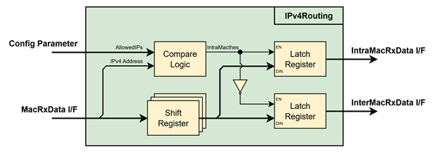
Figure 3 IPv4Routing Block Diagram
The routing logic is categorized into two primary paths:
· Intra-subnet Routing: This path handles packets that meet specific criteria for local or trusted communication. A packet is routed here only if its Destination IP matches one of the active allowed subnets (defined by CIDR prefixes) AND its Source IP matches a configured allowed host address.
· Inter-subnet Routing: All other valid IPv4 packets that do not meet the combined criteria for Path A are directed to this interface for further processing or external transmission.
Key Functional Specifications:
· The module supports up to 16 active IP/CIDR pairs, allowing for flexible network segmentation and access control.
· It utilizes a 64-bit wide AXI Stream-like interface to handle wire-speed 10GbE traffic, supporting byte-level enables and end-of-packet (Last) signaling.
· The design includes parameters to bypass ARP or strictly enforces UDP-only traffic checks (BYPASS_ARP and CHECK_UDP), providing an additional layer of protocol-level security.
Operations Sequence:
· Upon detecting the start of a new packet (MacRxValid asserted), the incoming MacRxData is fed into a Shift Register. This internal buffering delays the data stream just long enough for the routing logic to inspect the headers and determine the correct output path without losing line-rate throughput.
· The module extracts the EtherType, Source IPv4 Address, and Destination IPv4 Address from the buffered stream. These values are then compared against the hardware configuration parameters, including the local Address, the AllowedIPs table, and the corresponding AllowedCIDR masks to decide the routing direction.
· Once a routing decision is made for a specific packet, the module maintains that path for the remainder of the stream until the end-of-packet is reached, ensuring consistent delivery of the entire frame.
2.4 Ethernet Header Decapsulation Module
The Ethernet Header Decapsulation module is designed to strip Ethernet (L2) headers from incoming frames to extract the encapsulated IP (L3) payload. It processes 64-bit data from the 10GEMAC and aligns the payload for downstream processing.
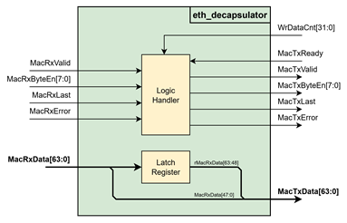
Figure 4 Ethernet Header Decapsulation Block Diagram
Key Features and Operational Logic:
· The module removes the 14-byte Ethernet header (Destination MAC, Source MAC, and EtherType). Since the header is not a multiple of 8 bytes, the module performs a shifter-based alignment to ensure the start of the IP payload is correctly positioned at the beginning of the 64-bit AXIS word.
· As the data is shifted and realigned, the module recalculates the MacTxByteEn signals. This logic ensures that the last word of a packet correctly reflects the actual number of valid bytes remaining after the header removal and shifting process.
· The logic is strictly feed-forward and does not implement internal buffering that would require pausing the incoming 10Gbps stream. Data flows through the module at line rate, maintaining the 64-bit AXIS throughput without the need for flow control back-pressure during the header removal process.
Operations Sequence:
· Upon detecting a new data transfer (MacRxValid asserted), the module evaluates the downstream buffer status using WrDataCnt[31:0]. If there is sufficient space to receive the new packet, the decapsulation process begins; otherwise, the incoming packet is discarded in its entirety to maintain stream synchronization.
· To handle the 14-byte header removal and realignment, the first two transactions of an asserted MacRxValid cycle are filtered and not passed to the output. During this phase, the module latches MacRxData[63:48] into the Latch Register. Valid data transmission to the downstream modules commences from the third transaction onward and continues until the end of the packet.
· The module manages the packet boundary transition based on the remaining byte count. If the final transaction contains more than 6 bytes of valid data, the logic automatically delays the MacRxLast signal by one clock cycle to ensure all realigned payload bytes are successfully transmitted.
2.5 Ethernet Header Encapsulation Module
The Ethernet Header Encapsulation module performs the reverse operation by wrapping L3 IP packets into IEEE 802.3 Ethernet frames. It handles MAC address insertion, EtherType identification, and ensures compliance with minimum Ethernet frame size requirements.
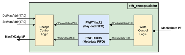
Figure 5 Ethernet Header Encapsulation Block Diagram
Key Features and Operational Logic:
· The module automatically inserts the Source MAC and Destination MAC addresses (configured via SrcMacAddr and DstMacAddr) and identifies the protocol (IPv4 or IPv6) from the first byte of the payload to set the correct EtherType (0x0800 or 0x86DD).
· Dual-FIFO Architecture:
o Payload FIFO: A 72-bit wide FWFT FIFO stores the data, byte enables, and error flags. It is sized to support Jumbo Frames (up to 9200 bytes).
o Metadata FIFO: A 16-bit wide FIFO stores the total byte count of each packet, allowing the transmission side to know the packet length before starting the read process.
· To comply with the Ethernet standard (minimum 60-byte payload excluding CRC), the module includes a Padding Logic. If the incoming IP packet is smaller than the minimum requirement, it automatically appends zero-padding to ensure the outgoing frame is valid.
· The module implements a threshold-based ready signal (rMacRxReady). It pauses new packet reception if the internal FIFO space is insufficient to accommodate a maximum-sized frame, preventing overflow during high-speed 10Gbps bursts.
Operations Sequence:
· When the FWFT4kx72 payload FIFO is ready to accept new data, the write control logic asserts the bus ready signal. It begins storing the incoming data stream as soon as valid packets are present on the interface.
· Upon detecting the end-of-packet signal, the write control logic updates the final packet size in the FWFT1kx16 metadata FIFO. This store-and-forward mechanism ensures that the entire packet is fully buffered before any transfer to the EMAC begins, meeting the hardware requirement for continuous operation.
· If the FWFT1kx16 metadata FIFO is not empty, the read control logic retrieves the packet size to initiate transmission.
o In the first clock cycle, the module outputs the DstMacAddr[47:0] followed by the upper 16 bits of the source address (SrcMacAddr[47:32]).
o In the subsequent clock cycle, it transmits the remaining SrcMacAddr[31:0] and the calculated EtherType (determined by inspecting the first byte and initial 2 bytes of the payload).
o Following the header insertion, the module reads the remaining data packet from the FWFT4kx72 and streams it to the EMAC once the destination bus is ready.
2.6 Ethernet Subsystem
The Ethernet Subsystem operates across multiple protocol layers, including the MAC (Media Access Control), PCS (Physical Coding Sublayer), and PMA (Physical Medium Attachment) layers. These layers work for interface with external devices using the 10G BASE-R standard. The WireGuard10G-IP communicates with the Ethernet MAC via a 64-bit AXI4-stream interface.
2.6.1 10G/25G Ethernet Subsystem
Alternatively, the 10G/25G Ethernet Subsystem can be used. This subsystem includes MAC, PCS, and PMA layers in a single IP block and can be generated using the Vivado IP catalog with the following configuration:
General
· Select Core : Ethernet MAC+PCS/PMA 64-bit
· Speed : 10.3125G
· Data Path Interface : AXI Stream
· Num of Cores : 2
PCS/PMA Options
· Base R/KR Standard : BASE-R
User Interface
· Control and Statistic Interface : Control and Status Vectors
The example of 10G/25G Ethernet Subsystem in Ultrascale
model is described in the following link.
https://www.xilinx.com/products/intellectual-property/ef-di-25gemac.html
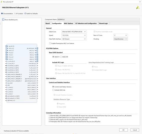
Figure 6 Example of AMD 10G/25G Ethernet Subsystem configuration page
3 CPU Firmware
After system boot-up, CPU initializes its peripherals such as UART and Timer. Then the supported command usage is displayed. The main function runs in an infinite loop to receive line command input from the user. Users can set the network and WireGuard parameter, display key materials using the supported commands. More details of the sequence in each command are described as follows.
3.1 Set FPGA IP Address
command> setdevIP <ddd.ddd.ddd.ddd>[/ddd]
The User employs this command to set the FPGA’s IP address in dotted-decimal format, with an optional subnet mask in CIDR notation. The default subnet mask is /24, and the default IP address is 192.168.7.42. This address represents the physical Ethernet interface rather than the WireGuard tunnel address.
Table 2 setip function
|
int setip(uint8_t *string, uint32_t *ip_set) |
|
|
Parameter |
string: ip address as string input from user ip_set: array stored IP address |
|
Return value |
0: Valid input, -1: Invalid input |
|
Description |
This function receives IP Address as string input and set value of ip_set array. |
3.2 Set FPGA Port Number
command> setdevport <ddddd|dynamic>
The User sets the FPGA’s UDP source port number using this command. If a numeric value (0-65535) is provided, the system utilizes it as a fixed static port. If the argument is set to “dynamic,” the system automatically assigns and increments a dynamic port starting from 51821 for each new connection. The default mode is dynamic.
Table 3 setport function
|
int setport(uint8_t *string, uint64_t *port_set) |
|
|
Parameter |
string: port number as string input from user port_set: array stored port number |
|
Return value |
0: Valid input, -1: Invalid input |
|
Description |
This function receives port number as string input and sets value of port_set array. |
3.3 Set FPGA MAC Address
command> setdevMac <hh-hh-hh-hh-hh-hh>
The User configures the FPGA’s Ethernet MAC address in hexadecimal format, with octets separated by hyphens. The default FPGA MAC address is 80-11-22-33-44-55, which is a unicast MAC address.
Table 4 setmac function
|
int setmac(uint8_t *string, uint64_t *mac_set) |
|
|
Parameter |
string: MAC address as string input from user mac_set: array stored mac address |
|
Return value |
0: Valid input, -1: Invalid input |
|
Description |
This function receives MAC Address as string input and set value of mac_set array. |
3.4 Set Gateway IP Address
command> setgatewayIP <ddd.ddd.ddd.ddd>
The User sets the network gateway IP address in dotted-decimal format. The default gateway IP address is 0.0.0.0.
3.5 Initialize TAI64 Timestamp
command> setTAI64 <hhhhhhhhhhhhhhhh>
The User initializes the TAI64 timestamp used in the WireGuard handshake initiation message. This value must be provided as a 16-character hexadecimal string.
3.6 Set FPGA Private Key
command> setprivkey <BASE64>
The User sets the FPGA’s WireGuard private key by providing a Base64-encoded string as input. The system accepts this Base64 format for ease of configuration, which is then decoded into a raw 256-bit (32-byte) key. This decoded 256-bit value is subsequently transferred to the WireGuard10G-IP core to be used as the primary static identity for the Noise handshake.
Table 5 wireguard_base64_decode function
|
bool wireguard_base64_decode(const char* str, uint8_t* out, size_t* outlen) |
|
|
Parameter |
str: Base64-encoded string to decode out: Output buffer for decoded bytes outlen: Pointer to buffer size; receives actual decoded length |
|
Return value |
True: on successful decoding, False: otherwise. |
|
Description |
This function decodes the Base64 input into a raw byte buffer for cryptographic use. |
3.7 Set WireGuard Interface Address IP
command> setWGaddressIP <ddd.ddd.ddd.ddd>
The User assigns the IP address for the FPGA’s WireGuard interface. This address is used for communication within the VPN tunnel.
3.8 Set Peer Public Key
command> setpeerpubkey <BASE64>
The User configures the FPGA’s WireGuard peer public key. The key must be the Base64-encoded X25519 public key corresponding to the peer’s private key.
3.9 Set Allowed IP
command> setallowsIP <ddd.ddd.ddd.ddd/ddd> ...
The User defines a list of up to 16 IP/CIDR pairs allowed to be routed through the WireGuard10G-IP. Setting 0.0.0.0/0 allows the User to route all traffic through the tunnel.
Table 6 set_allowed_ip function
|
void set_allowed_ip(int argc, char* argv[]) |
|
|
Parameter |
argc: Number of IP/CIDR arguments argv: Array of strings containing IP/CIDR entries |
|
Return value |
None. |
|
Description |
This function parses multiple IP/CIDR inputs and updates the hardware routing table. |
3.10 Set Endpoint IP Address
command> setendpointIP <ddd.ddd.ddd.ddd>[:ddddd]
The User sets the WireGuard peer’s endpoint IP address and port number. If the User omits the port, the system defaults to 51820. The default IP address is 192.168.7.25.
3.11 Set Pre-Shared Key
command> setpresharedkey <BASE64>
The User may optionally set a 32-byte symmetric pre-shared key (PSK) shared between the FPGA and the peer, provided as a Base64 string.
3.12 Set Persistent Keepalive
command> setpersistentkeepalive <ddddd>
The User sets the interval in seconds for persistent keepalive packets to ensure the bidirectional connection remains active through NAT or stateful firewalls. The User must provide a value within the valid 16-bit range, specifically from 0 to 65535 seconds. Setting the value to 0 allows the User to disable this feature, which is the default system state.
3.13 Show Ephemeral Private Key
command> showkey <on|off>
The User enables or disables the showkey mode, which controls the visibility of the ephemeral private key on the serial console. When this mode is active, the User receives the 256-bit ephemeral private key generated by the IP core. The system automatically processes this raw 256-bit data through a Base64 encoding function to provide a 44-character string format suitable for display and verification on the console.
Table 7 wireguard_base64_encode function
|
bool wireguard_base64_encode(const uint8_t* in, size_t inlen, char* out, size_t* outlen) |
|
|
Parameter |
in: Pointer to the 256-bit (32-byte) raw ephemeral key inlen: Length of input buffer (32 bytes) out: Output buffer for the resulting Base64 string outlen: Pointer to receive the actual encoded length |
|
Return value |
True: on successful encoding, False: otherwise. |
|
Description |
This function converts the raw 256-bit ephemeral private key into a Base64-encoded string for console display. |
3.14 Activate WireGuard
command> WGActivate
The User issues this command to commit all configured network and cryptographic parameters to the hardware and initiate the WireGuard handshake. The activation sequence is managed by the wg_process function, which follows a specific operational flow to ensure the WireGuard10G-IP core is synchronized with the Ethernet Encapsulation and Decapsulation modules.
Operational Sequence:
· The User’s command triggers a status check to ensure the IP core is in a state ready to accept configuration.
· The system writes the 256-bit cryptographic keys and network configurations into the hardware registers.
· The User triggers the WG_ACTIVATE signal. The system then waits for the hardware to acknowledge the configuration and finalize the initial handshake with the peer.
·
The system enters a continuous monitoring state where it displays
the active connection parameters, including Base64-encoded public keys and the
WireGuard virtual IP.
The User receives real-time updates on:
o Current operational state of the WireGuard IP.
o Total TX/RX data volume and timestamps.
o Optional ephemeral key details if enabled by the User.
· The User can terminate the session and exit the monitoring loop at any time by sending a Ctrl + C command via the serial console, which triggers the WG_DEACTIVATE sequence in the hardware.
Table 8 wg_process function
|
void wg_process() |
|
|
Parameter |
None. |
|
Return value |
None. |
|
Description |
Initializes the WireGuard IP core by writing cryptographic keys (preshared key, device private key, peer public key) and network parameters (IP/MAC addresses, ports, subnet mask, gateway) to hardware registers, then activates the tunnel and enters a monitoring loop that polls for statistics, key logs, and status until the user interrupts with Ctrl+C, after which it deactivates the tunnel or resets the core on failure. |
4 Revision History
|
Revision |
Date (D-M-Y) |
Description |
|
1.00 |
8-May-26 |
Initial version release |