DG LL-IP kernel reference design
Rev2.0 30-Jun-23
2.1 Xilinx Transceiver (PMA for 10GBASE-R)
2.4 LL10GEMACTxIF and LL10GEMACRxIF
2.6.1 TxEMACMux4to1 and TxEMACMux8to1
3 Other kernels in AAT (hardware)
4.4.1 Modified CMakeLists file
1 Introduction

Figure 1‑1 Low latency solution
Xilinx provides the Accelerated Algorithmic Trading (AAT) demo implemented by using Accelerator card to achieve low latency operation. The hardware is implemented to offload CPU and reduce the market data processing time. More details of AAT demo can be requested from Xilinx AAT Site.
To achieve the lower latency time, AAT design is modified by integrating LL10GEMAC-IP, UDP10GRx-IP, and TOE10GLL-IP. As shown in Figure 1‑1, Design Gateway provides two reference designs. The first design includes only LL10GEMAC-IP while the second design includes TOE10GLL-IP, UDP10GRx-IP, and LL10GEMAC-IP. The details of the first reference design that integrates only LL10GMEAC-IP can be downloaded from following link.
https://dgway.com/products/IP/Lowlatency-IP/dg_ll10gemac_aat_refdesign_xilinx_en.pdf
This document describes the second design that also includes UDP10GRx-IPs for decoding UDP/IP packet and TOE10GLL-IP for transferring TCP/IP packet. While UDP/IP and TCP/IP of default AAT demo use HLS code, UDP10GRx-IP and TOE10GLL-IP are designed by using HDL. Using UDP10GRx-IP and TOE10GLL-IP reduce Block RAM resource utilization and reduce the latency time of data processing. Also, the timing constraint is better and the maximum clock frequency of the application can be increased.
The interface of UDP10GRx-IP and TOE10GLL-IP are 32-bit interface at 322.266 MHz, so the adapter logic must convert the interface to be 64-bit interface at application clock with low-latency operation. The application layer of the AAT demo uses HLS code to help user update the design easily.

Figure 1‑2 The hardware of modified AAT demo by Low-latency IP core
Figure 1‑2 shows the hardware structure of the modified AAT reference design that integrates three DG low latency IPs - TOE10GLL-IP, UDP10GRx-IP, and LL10GEMAC-IP. Four Ethernet channels are implemented, three channels for transferring market data stream and trade order with Market data exchange and one channel for loopback test. Thus, four LL10GEMAC-IPs are included in the design.
The Market data exchange typically feeds the market data stream from two different routes. Two channels of ethernet are utilized by two 16-session UDP10GRx-IPs (UDP10GRx16SS) for processing the market data streams. UDP10GRx16SS is designed by using four UDP10GRx-IPs (one configured by master mode for session#0-#3 and three configured by slave mode for session#4-#15). More details of UDP10GRx16SS hardware are described in UDP10GRx-IP 16-session reference design document.
https://dgway.com/products/IP/Lowlatency-IP/dg_udp10grx_16ss_refdesign_xilinx_en.pdf
The result of AAT demo is the trade order message that is returned by TCP/IP module. TCP/IP module in the modified AAT design is designed by 32-session TOE10GLL-IPs (TOE10GLL32SS) which can process up to 32 TCP sessions at the same time. Though TOE10GLL32SS consists of thirty-two TOE10GLL-IPs, user can update the parameter assigned in HDL to reduce the number of supported TCP sessions for resource optimization. More details of 32-session TOE10GLL-IP are described in TOE10GLL-IP 32-session reference design document.
https://dgway.com/products/IP/Lowlatency-IP/dg_toe10gllip_32ss_refdesign_xilinx_en.pdf
In AAT demo, the market data output from two UDP10GRx16SS modules are fed to Line Handler, Feed Handler, Orderbook, Pricing Engine, and Order Entry, respectively. All kernels are designed by HLS. Pricing Engine has the rule for the market data monitoring. When the rule is matched, it activates the Order Entry to create the trade order. Each hardware kernel is controlled by CPU via Config port.
Ethernet Kernel has three interfaces for connecting with others � EMAC interface, UDP interface, and TCP interface. The EMAC interface is connected with the external pin and has its own clock domain � PMA clock which is equal to 322.266 MHz. While UDP and TCP interface are run in the application clock domain which can be configured by the system. In this demo, the application can be configured to 320 MHz. As two clock domains are applied in Ethernet Kernel, there are the adapter logic inside Ethernet Kernel to convert the interface of TOE10GLL-IP, UDP10GRx-IP, and LL10GEMAC-IP to AXI4-ST standard and convert the clock domain from local clock (PMA clock) to the application clock.
The AAT hardware can be accessed from CPU in the host-PC through software shell and Xilinx Runtime for controlling system and reading status. Ethernet kernel includes the register modules for setting parameters and reading status of DG LL-IPs. The interface of the register with the application is AXI4-Lite bus standard. The software shell that runs on Linux is modified because of the change of the AAT hardware that integrates DG LL-IPs.
2 DG LL-IP kernel (Hardware)

Figure 2‑1 DG LL-IP kernel block diagram
The DG LL-IP kernel is integrated to the Accelerated Algorithmic Trading (AAT) system. It consists of TCP module that supports 32 sessions (TOE10GLL32SS), UDP module that supports 16 sessions (UDP10GRx16SS), and loopback module by EMAC for internal test. TCP module and UDP module require the Control interface for parameter configuration such as MAC address by Shell via LAxi2Reg module. Also, the status of TCP module, UDP module, and EMAC for system monitoring can be read via LAxi2Reg. AXI4-Lite bus is the standard for connecting with user module.
LL-Network kernel has four channels (Ch#0 � Ch#3) for transferring Ethernet packet via four 10G Ethernet connections. Each channel uses AXI4-Stream interface for transferring the control and data stream. Ch#0 is mapped to TCP module for transferring order message from Order Entry kernel. Ch#1 and Ch#2 are mapped to UDP module for transferring market data to Line handler kernel. Ch#3 is mapped to EMAC-IP for loopback test.
Ch#0 has AXI4-ST for transferring control/status stream, Tx data stream, Rx data stream. While Ch#1 and Ch#2 has only AXI4-ST for transferring Rx data stream. Finally, Ch#3 has AXI4-ST for transferring Tx data stream and Rx data stream.
To achieve the lowest latency time for processing Ethernet packet with LL10GEMAC-IP, TOE10GLL-IP and UDP10GRx-IP are designed to connect with LL10GEMAC-IP directly. Therefore, TOE10GLL-IP and UDP10GRx-IP are run in the local clock domain which is the same clock as LL10GMEAC-IP, MacTxClk and MacRxClk. To support multi-session feature, 32 TOE10GLL-IPs are placed in TOE10GLL32SS while 16 UDP10GRx-IPs are placed in UDP10GRx16SS. TxEMACMux is applied to transfer transmitted packet from many TOE10GLL-IPs or UDP10GRx-IPs to one LL10GEMAC-IP.
To transfer the data stream with other kernels via Ch#0 AXI4-ST � Ch#3 AXI4-ST#3, the interface must be run by using application clock, AppClk, which can be configured its frequency value by the tool. Therefore, all user interfaces of TOE10GLL-IPs, UDP10GRx-IPs, and LL10GEMAC-IP require to convert the clock domain to AppClk by using the adapter logics. The adapter logics are applied to convert the data bus width and the bus standard. PipeReg is applied to be asynchronous module for Control interface to set TOE10GLL-IP and UDP10GRx-IP parameters.
LL10GEMAC-IP implements the Ethernet MAC layer and PCS layer with ultra-low latency time. It needs to connect Xilinx Transceiver which is configured to be PMA module for 10GBASE-R interface. When using the transceiver to be PMA module with low-latency feature, PMARstCtrl must be applied to control reset sequence of Xilinx Transceiver.
More details of each module inside DG LL-IP kernel are described as follows.
2.1 Xilinx Transceiver (PMA for 10GBASE-R)
PMA IP core for 10Gb Ethernet (BASE-R) can be generated by using Vivado IP catalog. In FPGA Transceivers Wizard, the user uses the following settings.
· Transceiver configuration preset : GT-10GBASE-R
· Encoding/Decoding : Raw
· Transmitter Buffer : Bypass
· Receiver Buffer : Bypass
· User/Internal data width : 32
The example of Transceiver wizard in Ultrascale model is described in the following link.
https://www.xilinx.com/products/intellectual-property/ultrascale_transceivers_wizard.html
2.2 LL10GEMAC
The IP core by Design Gateway implements low-latency EMAC and PCS logic for 10Gb Ethernet (BASE-R) standard. The user interface is 32-bit AXI4-stream bus. Please see more details from LL10GEMAC-IP datasheet on our website.
https://dgway.com/products/IP/Lowlatency-IP/dg_ll10gemacip_data_sheet_xilinx_en.pdf
2.3 PMARstCtrl
When the buffer inside Xilinx Transceiver is bypassed, the user logic must control reset signal of Tx buffer and Rx buffer. The module is designed by state machine to run following step.
1) Assert Tx reset of the transceiver to �1� for one clock cycle.
2) Wail until Tx reset done, output from the transceiver, is asserted to �1�.
3) Finish Tx reset sequence and de-assert Tx reset, user interface output, to allow the user logic beginning Tx operation.
4) Assert Rx reset to the transceiver.
5) Wait until Rx reset done, output from the transceiver, is asserted to �1�.
6) Finish Rx reset sequence and de-assert Rx reset, user interface output, to allow the user logic beginning Rx operation.
2.4 LL10GEMACTxIF and LL10GEMACRxIF
These modules are applied to interface with LL10GEMAC-IP by using 32-bit AXI4-Stream bus. While another side for connecting to loopback module uses 64-bit AXI4-Stream bus. It also includes clock-domain crossing logic. Please see more details from LL10GEMAC-IP reference design on our website.
https://dgway.com/products/IP/Lowlatency-IP/dg_ll10gemac_aat_refdesign_xilinx_en.pdf
2.5 UDP10GRx16SS

Figure 2‑2 UDP10GRx16SS block diagram
The UDP10GRx16SS receives the market data stream from LL10GEMAC-IP. Up to 16 sessions can be monitored at the same time. After each UDP10GRx-IP finishes packet processing, the payload data of the valid is extracted and forwarded to Line Handler. The adapter logic (UDPRx16SS2AXI4) converts 32-bit data stream from four UDP10GRx-IPs to 64-bit data bus on AppClk domain. Also, the session number of the extracted payload data is defined on Metadata bus. Sometimes, UDP10GRx-IPs must transmit the packet to be the response of the request such as ICMP packet for round-trip time monitoring. 4-to-1 multiplexer (TxEMACMux4to1) is integrated to select transmitted packet from one of four UDP10GRx-IP to LL10GMEAC-IPs. The details of UDPRx16SS2AXI4 and TxEMACMux4to1 are available on the 32-session reference design document following this link.
https://dgway.com/products/IP/Lowlatency-IP/dg_udp10grx_16ss_refdesign_xilinx_en.pdf
The operation of UDP10GRx16SS is controlled by the application via Shell and PipeReg. The network parameters such as MAC address, IP address, and port number are assigned by the application while the current status of all UDP10GRx-IPs such as the connection status is returned to PipeReg for system monitoring.
2.5.1 TxEMACMux4to1
This module is data switch to select one of four UDP10GRx-IPs to transfer Ethernet packet to LL10GEMAC-IP.
2.5.2 UDP10GRxIP
The IP core by Design Gateway is UDP/IP engine for decoding UDP/IP packet that is transmitted by EMAC. UDP payload is extracted and then forwarded to the user with very low latency time. One IP supports up to four UDP sessions. More details of UDP10GRx-IP are described in UDP10GRx-IP datasheet, provided on our website.
https://dgway.com/products/IP/Lowlatency-IP/dg_udp10grxip_data_sheet_xilinx_en.pdf
2.5.3 UDPRx16SS2AXI4
This module is the adapter to connect the user interface of four UDP10GRx-IPs to the external logic. The user interface of UDP10GRx-IP is 32-bit data interface while the interface of the external logic is 64-bit AXI4-Stream bus (UserData) and 16-bit AXI4-Stream bus (Metadata). Also, asynchronous logic is included to convert clock domain.
Note: 16-bit AXI-ST (MetaData) is expanded to 64-bit AXI-ST, outside of this module, for AAT reference design interface compatibility. The upper bits are filled by zero value.
2.6 TOE10GLL32SS

Figure 2‑3 TOE10GLL32SS block diagram
The TOE10GLL32SS connects with the Order entry for transmitting the order message to the target. Up to 32 sessions can be supported by this module. Meanwhile, TOE10GLL32SS can receive the data from the target device and then returns the TCP payload data to the Order entry. Therefore, the data interface of TOE10GLL32SS has both Tx direction and Rx direction. 64-bit Tx and Rx Metadata bus are applied to assign the session number of the transferred data on 64-bit Tx and Rx data bus. Comparing to UDP10GRx16SS, there are three additional AXI4-ST interfaces for sending the command (32-bit Cmd), requesting the current status (32-bit GetStatus), and returning the status (32-bit RespStatus). The control interface of 32 TOE10GLL-IP is connected to PipeReg to receive the parameters such as MAC address, IP address, and Port number from the application via Shell and PipeReg. Also, the current IP status of every TOE10GLL-IP is returned to PipeReg for system monitoring.
Three adapter logics are applied to connect with Order Entry. First is TOEAsyncAXICmd to connect with the command/status AXI4-ST bus and convert clock domain between AppClk and MacTxClk. Second is TOETx32SSAXI4 to connect with AXI4-ST bus of Tx data and convert clock domain between AppClk and MacTxClk. Third is TOERx32SSAXI4 to connect with AXI4-ST bus of Rx data and convert clock domain between AppClk and MacRxClk. While two TxEMACMux modules are included to support 32 TOE10GLL-IPs. Four TxEMACMux8to1 and one TxEMACMux4to1 are applied. More details of each module are described as follows.
2.6.1 TxEMACMux4to1 and TxEMACMux8to1
This module is data switch to select one of four or eight modules to transfer ethernet frame to LL10GEMAC-IP. Four TxEMACMux8to1 are applied to receive 32-bit Tx data stream from 32 TOE10GLL-IP. Four output ports from TxEMACMux8to1 are connected to one TxEMACMux4to1 to select only one active stream for transferring to EMAC. Please see more details from TOE10GLL-IP 32-session reference design on our website.
https://dgway.com/products/IP/Lowlatency-IP/dg_toe10gllip_32ss_refdesign_xilinx_en.pdf
2.6.2 TOE10GLLIP
TOE10GLL-IP is the IP core provided by Design Gateway that implements the TCP/IP stack and offload engine for the low latency solution. User interface has two signal groups, i.e., control signals and data signals. The IP can be configured to run in two modes: Cut-through mode and Simple mode. Also, Tx buffer can be configured to balance resource utilization and test performance. TOE10GLL-IP in this reference design is configured to Cut-through mode and 8 KB Tx buffer. Most control signals are mapped to Control interface of PipeReg while the command for opening/closing the port is mapped to 32-bit Cmd AXI4-ST I/F of OrderEntry. Also, the current status of TOE10GLL-IP is returned to PipeReg and 32-bit Resp Status AXI4-ST I/F of OrderEntry. More details of TOE10GLL-IP are described in datasheet.
https://dgway.com/products/IP/Lowlatency-IP/dg_toe10gllip_data_sheet_xilinx_en.pdf
2.6.3 TOEAsyncAXICmd
Three AXI4-ST interfaces are connected to TOEAsyncAXICmd module. First is 32-bit Cmd AXI4-ST which is renamed to UReqCmd interface. This interface is applied to send three commands to one of thirty-two TOE10GLL-IPs by assigning to 7-bit signals (2 bits for the command � Active open, Passive open, and Active close and 5 bits for session number). Second is 32-bit GetStatus AXI4-ST which is renamed to UReqSts interface. This interface is applied to request the status from one of thirty-two TOE10GLL-IPs. 5-bit data is the requested session number. After that, the status of the requested TOE10GLL-IP is returned to the third AXI4-ST interface (32-bit RespStatus AXI4-ST that is renamed to URlySts interface). More details of AXI4-ST Cmd and AXI4-ST Status are described as follows.
Cmd AXI4-ST I/F (UReqCmd I/F)
Bit[6:0] of UReqCmdData is applied to send the command and the session number. Bit[4:0] is the requested session number while bit[6:5] is TCPCmd[1:0] of TOE10GLL-IP. When one data is received, one command is transferred to requested TOE10GLL-IP. Before sending the new request, it needs to confirm that the requested TOE10GLL-IP is ready to receive the new command.

Figure 2‑4 Cmd AXI4-ST I/F timing diagram
1) When the new command is requested by the user (UReqCmdValid=�1� and UReqCmdReady=1�), seven lower bits are loaded. Bit[1:0] which is the command value is loaded to rUCmdTCPCmd while bit[6:2] which is the session number is loaded to rUCmdSession. Meanwhile, rUReqCmdBusy is asserted to �1� to start forwarding the command from Clk domain to MacClk domain (asynchronous register). UReqCmdReady is de-asserted to �0� to block the new request until the operation is done.
2) rUReqCmdBusy in Clk domain is forwarded to MacClk domain by using three registers - rReqCmdBusyMac[0] � [2]. All signals are asserted after rUReqCmdBusy is asserted.
3) In Figure 2‑4, the active session is no.0. Thus, bit0 of U2TOETCPCmdValid is asserted to �1� along with the command on U2TOETCPCmd. 32 bits of U2TOETCPCmdValid are applied to assert the request to 32 TOE10GLL-IPs. It is the same time as rUReqCmdBusyMac[2] asserted. Therefore, rUReqCmdBusyMac[2] is applied to show the command request on MacClk domain is done.
4) rUReqCmdBusyMac[2] on MacClk domain is forwarded to Clk domain by asynchronous register - rUReqCmdBusyAck[0].
5) rUReqCmdBusyAck is applied to confirm that the command request on MacClk domain is done. Thus, rUReqCmdBusy is de-asserted to �0� after rUReqCmdBusyAck[0] is asserted for two clock cycles. After that, rUReqCmdBusy is forwarded to asynchronous register in following sequence:
rUReqCmdBusy-> rUReqCmdBusyMac[0]-> [1] -> [2] -> rUReqCmdBusyAck[0].
Thus, all signals are de-asserted to �0�.
6) After the operation is done (rUReqCmdReady=�0� and rUReqCmdBusyAck[1]=�0�), rUReqCmdReady is re-asserted to �1� to accept the new command request from user.
Status AXI4-ST I/F (UReqSts I/F and URlySts I/F)
Bit[4:0] of UReqStsData is the request session number to get the latest status. The status is returned on URlyStsData[12:0] (5-bit session number, busy flag, connection ON/OFF, Initial done flag, and 5-bit TOE10GLL-IP state). The new request can be received after the status is returned completely.

Figure 2‑5 Status AXI4-ST I/F timing diagram
1) When the status request is received (UReqStsValid=�1� and UReqStsReady=�1�), the request session on UReqStsData[4:0] is loaded to rUReqStsSSLat signal. Also, the state changes to stGenReq to start the operation. UReqStsReady is de-asserted to �0� to block the new request until the operation is done. The active session is also forwarded to MacClk domain by using asynchronous register (rUReqStsSSMac0).
2) In stGenReq, the request signal (rStsReq) is asserted to �1� to start status request operation. This signal is forwarded to MacClk domain by using three registers � rStsReqMac[0] � [2].
3) Also, the active session number (rUReqStsSSMac0) is applied to select the status from thirty-two TOE10GLL-IPs to return on URlyStsData bus. To select one of thirty-two TOE10GLL-IP status, two multiplexers are applied � four Mux8-to-1 and one Mux4-to-1. In Figure 2‑5, the status of TOE10GLL#16 is selected because rUReqStsSSMac0 is equal to 16. rRlyStsxx2 is valid before rStsReqMac[2] is asserted to �1�.
4) The request signal on MacClk domain (rStsReqMac) is returned to Clk domain to be acknowledgement signal by using two asynchronous registers (rStsReqAck[0] � [1]). It confirms that the request is asserted on MacClk completely. Also, the returned status on rRplyStsxx2 is returned to Clk domain via asynchronous register (URlyStsData).
5) When rStsReqMac[2] is asserted, the state changes to stRlySts. In this state, URlyStsValid is asserted to �1� to be return the status on URlyStsData. Also, rStsReq is de-asserted to �0� to finish this request.
6) If the status is accepted (URlyStsValid=�1� and URlyStsReady=�1�), the state changes to stWtDone. Also, URlyStsValid is de-asserted to �0�.
7) When rStsReq is de-asserted, the signal is forwarded to asynchronous register in following sequence: rStsReqMac[0] -> [1] -> [2] -> rStsReqAck[0] -> [1]. All signals are de-asserted to �0� to clear the request.
8) After all requests in the logic are cleared (rStsReqAck[1] which is the last signal in the asynchronous chain is equal to �0�), the state returns to stIdle. After that, UReqStsReady is re-asserted to �1� to accept the new status request.
2.6.4 TOETx32SSAXI4
This module is the adapter to transmit the order message from the OrderEntry kernel to one of thirty-two TOE10GLL-IPs. The interface of OrderEntry consists of 64-bit UDataTx I/F and 33-bit UMetaDataTx I/F which are AXI4-ST standard running on Clk domain (AppClk of the system). While the interface of TOE10GLL-IP is 32-bit data I/F with the parameters that are decoded from UMetaDataTx I/F on MacClk domain (MacTxClk of the system). Thus, UDataTx I/F and UMetaDataTx I/F must be forwarded to the TOE10GLL-IP with AXI4-stream crossing clock domain. Also, 64-to-32-bit data width conversion are performed. This module is designed for achieving low-latency performance. Thus, there are some limitations for using this module listed below.
· MacClk frequency over Clk frequency ratio must be less than two.
· If UDataTxValid is dropped during the transmission and finally the read logic cannot get the new data in time, the target TOE10GLL receives the error packet. According to TOE10GLL-IP, when the incorrect input is received, the connection must be reset.

Figure 2‑6 TOETx32SSAXI4 block diagram
As shown in Figure 2‑6, there is RAMTDP512x72to36 to store UDataTx I/F and the Latch register to store UMetaTx I/F. The Ram and the latch are divided to two banks for running as double buffer. The left-hand side is the logic to write RAM and the Latch which is run on Clk. While the right-hand side is the logic to read RAM and the Latch which is run on MacClk domain. CDC (clock domain crossing) is included to transfer the flow control signals across clock domain, i.e., rUDataTxStartLat (start transfer data to TOE) and rTOERdEndLat (transfer data to TOE complete).
RamTDP512x72to36 and Latch
The RamTDP512x72to36 module is block memory which is configured to be True-dual port block RAM type with asymmetric data width feature. 72-bit data width in Clk domain is converted to 36-bit data width in MacClk domain. 36-bit data consists of 32-bit data, 2-bit encoded keep, 1-bit last flag, and 1-bit data valid. 1-bit data valid can be written by both Write controller and Read controller. The write controller writes �1� when the new data is written to RAM in each address. The read controller writes �0� when the data is read from RAM in each address. This flag is applied for checking underflow condition by the read controller which is found when the write controller pauses data transmission for many cycles.
The RamTDP512x72to36 module is divided into 2 banks to store the AXI4-Stream data from user. The first bank (ch#0) has a memory address at 0 to 255 and the second bank (ch#1) has a memory address at 256 to 511. Each bank stores one packet, so the maximum packet length is equal to the bank size, 2048 bytes (256 x 64-bit). The bank is switched when the write controller/the read controller finishes to write/read each packet.
Similarly, the latched register is divided into 2 parts to store the meta data of two packets. 33-bit meta data contains 11-bit packet size, 16-bit data checksum, push flag, and 5-bit session ID number. The packet size, data checksum, and push flag are the parameters that need to forwarded to TOE10GLL-IP when sending the first data of a packet while the session ID number is applied to select one of thirty-two TOE10GLLs.
Write controller
User flow controller asserts UDataTxReady to accept the new packet transmission when the next RAM bank is free. The address is counted-up, starting from address=0 to store the first data of each packet. After transferring final data of a packet, MSB of the address is inverted to switch the active bank. Besides, User flow controller asserts the start transfer flag (rUdataTxStartLat) when the first data of the new packet and the meta data are received. This signal is forwarded to the State M/C (inside the read controller) via CDC to start the packet transmission to TOE10GLL-IP. After the State M/C transfers the final data of packet from each bank, End flag (rTOERdEndLat) will be asserted. When End flag is asserted, the busy flag to show the RAM status (�0�: Free, �1�: Full) will be cleared. Thus, User flow control can use the free bank to store the new packet.
Read controller
State machine controls data flow to forward the read data from RAM to TOE10GLL-IP. The read operation is started when the Start flag on MacClk (rTOERdStartLat) is asserted and the active TOE10GLL-IP is ready to receive data (U2TOETxReady=�1�). The active TOE10GLL-IP is decoded from a part of the Meta data (aTOETxSSID). To transfer the data, U2TOETxValid of the active TOE10GLL-IP is asserted to �1�. The read address is created by State machine. The RAM and the parameters from the latch are read and forwarded to TOE10GLL-IP continuously in each packet. If the read controller detects underflow flag (data valid=�0�), it determines that now the last data is transferred and asserts the last flag to TOE10GLL-IP. In this condition, the packet length and the checksum of the packet that transmit to TOE10GLL-IP will not be matched with the data packet. Error will be found in TOE10GLL-IP. When the final data is transmitted successfully, State machine will switch the RAM bank for the next packet transmission and End flag(rTOERdEndLat) is asserted.

Figure 2‑7 TOETx32SSAXI4 (Write RAM I/F) timing diagram
1) When the new data packet is received (UDataTxValid=�1�) and RAM is free to store the new packet (UDataTxReady=�1�), the received data (UDataTxData) is written to the RAM by asserting rU2TxRamWrEn to �1�. 72-bit Write data to RAM (rU2TxRamWrData) is formatted to two 36-bit data which consists of 32-bit data, 2-bit encoded byte enable, last flag, and data valid flag. Bit[7:0] of Write RAM address (rU2TxRamWrAddr) is up-counted, starting from 0 while bit[8] is bank address that is loaded from rUserTxChSel.
2) When the meta data that contains the parameters of the data packet is received (UMetaTxValid=�1� and UMetaTxReady=�1�), the meta data is loaded to the latched register of the active channel (Ch#0 when rUserTxChSel=�0�). There is one meta data for each packet. Therefore, UMetaTxReady is de-asserted to �0� to block the next data after receiving the meta data. It is de-asserted until the logic is ready to receive the new data packet.
3) When the meta data (UMetaTxData) and the first data (UDataTxData) are received, the start flag of the active channel is asserted (rUDataTxStartLat[0]=�1� when rUserTxChSel=�0�).
4) In the next clock after rUDataTxStartLat is asserted, rUserTxChBusy of the active channel is asserted to �1� to block the new received data to this RAM bank.
5) The start flag on Clk domain (rUDataTxStartLat) is transferred to MacClk domain. rUDataTxStartAck is asserted to �1� when the start flag on MacClk domain is asserted. After rUDataTxStartAck is asserted, rUDataTxStartLat is de-asserted to clear the request of this channel.
6) The data is stored to the RAM until the final data is received. After the final data of a packet is received (UDataTxValid=�1� and UDataTxLast=�1�), UDataTxReady is de-asserted to �0� to block the new data packet. It is de-asserted until the logic is ready to receive the new data packet. If the last data (UDataTxData) and one meta data (UMetaTxData) are received completely, the active channel (rUserTxChSel) toggles the value. Also, bit[7:0] of the write RAM address are reset to 0 to store the next data packet from the start address.
7) When the active channel is switched and the new RAM bank is ready to receive data (rUserTxChBusy of the new channel = �0�), UMetaTxReady and UDataTxReady are re-asserted to �1� to receive the new meta data and the new data packet. After that, the data of the new packet is written to the RAM from the first address of the new bank. Also, the meta data is loaded to the latch register of the new channel.
8) Similar to step 3), the start flag of the new channel is asserted to �1� (rUDataTxStartLat[1] when rUserTxChSel=�1�) to request the packet forwarding to the read controller logic.
9) If the packet from RAM is forwarded to TOE10GLL-IP completely, rUserTxChBusy of the first channel (Ch#0) is de-asserted to �0� to show the RAM is free to store the new packet. Thus, UDataTxReady and UMetaTxReady can be asserted to �1� when the active channel is switched to the first channel (Ch#0).

Figure 2‑8 TOETx32SSAXI4 (Read RAM I/F) timing diagram
1) The meta data from the latch register is loaded to aTOETxSSID (the active TOE10GLL-IP number), U2TOETxPkLen (packet length of TOE10GLL-IP), and U2TOETxCsum (TCP data checksum of TOE10GLL-IP). The active channel is controlled by rTOERdChSel. The operation is started when rTOERdStartLat[0] or [1] is asserted in stIdle. The state changes to stChkReady.
2) U2TOETxReady of the active TOE10GLL-IP (Ch#4 when aTOETxSSID=4) is checked. The state changes to stRead when U2TOETxReady is asserted. Meanwhile, wT2URamRdAddr is up-counted to read the next data and wT2URamWrEn is asserted to clear RAM that is completely read.
3) In stRead, the data from RAM and the meta data from latch register are transferred to the active TOE10GLL-IP. 36-bit read data from RAM is forwarded to be 32-bit data (U2TOETxData), last flag (U2TOETxEOP), and decoded byte enable (U2TOETxByteEn). Also, U2TOETxPkLen and U2TOETxCsum are valid to be the parameters for TOE10GLL-IP. The data and the control flag are forwarded from RAM until the final data is transferred.
4) When the final data is forwarded (U2TOETxEOP=�1�), U2TOETxValid is de-asserted. Also, the state changes to stEnd.
5) When the state is stEnd, rTOERdChSel toggles the value to switch the active channel. Also, wT2URamRdAddr is reset to be the start RAM address of the new channel and rTOERdEndLat is asserted to show the complete status. After that, the state returns to stIdle.
6) The packet of the new channel is forwarded from RAM to the active TOE10GLL-IP (Ch#9 when aTOETxSSID=9). Firstly, U2TOETxReady of the active TOE10GLL-IP is monitored. After that, the state changes to stChkReady and then stRead to forward the packet until the final data is transferred.
7) The end flag (rTOERdEndLat) which is complete status is forwarded to Clk domain. It is applied to de-assert busy flag (rUserTxChBusy). rTOERdEndAck is asserted when the end flag on Clk domain is asserted completely. After that, rTOERdEndLat is de-asserted to clear the complete status.
2.6.5 TOERx32SS2AXI4

Figure 2‑9 TOERx32SS2AXI4 Block diagram
One TOE10GLL-IP supports to receive one session data from EMAC. When 32-session data is required, thirty-two TOE10GLL-IPs must be integrated. The 32-session data must be forwarded to the Order Entry for processing. The adapter logic � TOERx32SS2AXI4 is applied to transfer the data stream of thirty-two Rx Data I/F by TOE10GLL-IP to two AXI4-ST bus of the Order Entry (64-bit UserData and 64-bit MetaData). 64-bit UserData AXI4-ST is applied to transfer 32-session TCP payload data while 64-bit MetaData AXI4-ST is applied to send the session number. In this design, there are 32 sessions, so bit[4:0] of MetaData is enough to define session number.
In this reference design, all TOE10GLL-IPs connect with the same EMAC, so there is one session data can be transferred from TOE10GLL-IPs each time. The data stream from TOE10GLL-IPs that is synchronous on MacClk must be converted to Clk domain. Also, the session number must be encoded with the data stream. Small asynchronous FIFO with FWFT type (AsyncFWFTFifo16x79) is applied to convert 32-bit data bus in MacClk domain (322.265 MHz) to 64-bit data bus in Clk domain (independent clock). Data size in FIFO is 79 bits (64-bit data, 8-bit byte enable, end-of-packet flag, error flag, and 5-bit session ID). The logics inside TOERx32SS2AXI4 are divided to two groups, 32-bit to 64-bit data converter and alignment with Mux8to1 for writing FIFO and FIFO read controller for reading FIFO.
Four Mux8to1 modules are applied to reduce the number of inputs in 32-bit to 64-bit data converter and alignment. Eight TOE10GLL-IPs connects to Mux8to1 and the output interface of each Mux8to1 connects to the data converter and alignment. rTCPRx has four indexes � [0], [1], [2], and [3] for mapping to TOE10GLL#0-#7, #8-#15, #16-#23, and #24-#31 accordingly.
Figure 2‑10 shows timing diagram of 32-bit to 64-bit data converter and alignment with Mux8-to1 to write FIFO when total amount of received data from TOE10GLL-IP#0 is aligned to 64-bit. Thus, the dummy data is not filled in this case. While Figure 2‑11 shows the example when total amount of received data is not aligned to 64-bit and one dummy data must be filled.

Figure 2‑10 Timing diagram to write FIFO without filling dummy data
1) When the new packet is received from TOE10GLL-IP (TOERxValid[x]=�1� and TOERxSOP[x]=�1�), the session ID (rSSIDLat) is decoded from TOERxValid. For instance, rSSIDLat is equal to 0 when bit0 of TCPRxValid is asserted. RxData I/F of the active TOE10GLL-IP (TCPRxValid, TCPRxSOP, TCPRxEOP, TCPRxData, TCPRxByteEn, and TCPRxError) is fed to Mux8to1. After that, the output of Mux (rTCPRx* I/F) is fed to the data converter and alignment. Thus, the latency time of rRxDataH (the data input to FIFO) from TCPRxData is equal to 2 cycles (1 cycle from Mux8to1 and 1 cycle from the data converter and alignment). While TCPRxValid[0] is asserted, rWordHEn is toggled to check the amount of received data in 64-bit unit. Also, rRxDataL loads the value from rRxDataH to be the 32 lower bits of 64-bit write data to FIFO.
2) When two 32-bit data is received (rTCPRxValid[0]=�1� and rWordHEn=�1�), 64-bit data (rRxDataH and rRxDataL) is stored to FIFO by asserting FIFO write enable (rU2AFfWrEn) to �1�.
3) When the data is not ready, TOE10GLL-IP de-asserts TCPRxValid to �0� to pause data transmission. Data valid output from Mux8to1 and the logic to write the FIFO also pause the operation (rTCPRxValid[0]=�0� and rU2AFfWrEn=�0�).
4) When the final data of a packet is received with 64-bit alignment (rTCPRxValid[0]=�1�, rTCPRxEOP[0]=�1�, and rWordHEn=�1�), the final 64-bit data is stored to FIFO without filling dummy data to align 64-bit.
Note: rTCPRxValid[0] and rTCPRxEOP[0] are the output of Mux8to1 which are asserted after TCPRxValid[0] and TCPRxEOP[0] are asserted for one clock cycle.

Figure 2‑11 Timing diagram to write FIFO with filling dummy data
1) When the final data of a packet is received and total amount of received data is not aligned to 64-bit (rTCPRxValid[1]=�1�, rTCPRxEOP[1]=�1�, and rWordHEn=�0�), rDummyEn is asserted to �1� to fill one dummy 32-bit data.
Note: rTCPRxValid[1] and rTCPRxEOP[1] are the outputs of Mux8to1. They are asserted after TCPRxValid[13] and TCPRxEOP[13] asserted for one clock cycle.
2) After rDummyEn is asserted, rRxDataL loads the last data from rRxDataH while the dummy data is loaded to rRxDataH. Meanwhile, rU2AFfWrEn is asserted to �1� to store the final data which consists of 32-bit final data on rRxDataL and 32-bit dummy data on rRxDataH to FIFO.
Figure 2‑12 shows timing diagram of FIFO Read controller to read FIFO and forwards the read data to the OrderEntry via 64-bit UserData AXI4-ST bus. Meanwhile, the session number is assigned via 16-bit MetaData AXI4-ST bus. One MetaData to show session number of data stream is transferred when the first UserData is transferred.
FIFO in the design is FWFT type, so Read data of FIFO (U2AFfRdData) is valid at the same time as Read enable of FIFO (wU2AFfRdAck) is asserted to �1�. 79-bit read data from FIFO (U2AFfRdData) is assigned as follows.
Bit[63:0] : 64-bit data
Bit[71:64] : 8-bit byte enable
Bit[72] : Last flag to show end of packet
Bit[73] : Error flag of the packet
Bit[78:74] : 5-bit Session ID

Figure 2‑12 Timing diagram of FIFO Read controller
1) rRd1stEn is asserted to �1� when the read data from FIFO is the first data of a packet. FIFO read enable (wU2AFfRdAck) is asserted to �1� by two methods.
i) If the data is the first data of a packet (rRd1stEn=�1�), wU2AFfRdAck is asserted to �1� when FIFO is not empty (U2AFfEmpty=�0�).
ii) If the data is not the first data of a packet (rRd1stEn=�0�), wU2AFfRdAck is asserted to �1� when FIFO is not empty (U2AFfEmpty=�0�) and RxAxiSReady=�1�.
FIFO is FWFT type, so the read data of FIFO (U2AFfRdData) is valid at the same clock as wU2AFfRdAck asserted.
2) Bit[78:74] of U2AFfRdData is loaded to Meta data output (RxAxiSMetaData). It is the session ID of the data stream. Meta data is transmitted by asserting valid signal (RxAxiSMetaValid=�1�) when the first data is read (wU2AFfRdAck=�1� and rRd1stEn=�1�). Meanwhile, bit[63:0] of U2AFfRdData is loaded to User data output (RxAxiSData) and the data valid signal is asserted (RxAxiSValid=�1�). Data stream is valid (RxAxiSValid=�1�) when FIFO read enable is asserted (wU2AFfRdAck=�1�). Besides, rRd1stEn is de-asserted to �0� after the first data is read from FIFO.
3) After reading the first data, the read enable of FIFO (wU2AFfRdAck) is controlled by FIFO empty (U2AFfEmpty) and User ready (RxAxiSReady). The read enable is asserted to �1� when U2AFfEmpty=�0� and RxAxiSReady=�1�. While data is read from FIFO, U2AFfRdData[63:0] is loaded to be RxAxiSData.
4) RxAxiSMetaValid is de-asserted to �0� after acknowledge signal is asserted (RxAxiSMetaReady=�1�).
5) wU2AFfRdAck is de-asserted to �0� to pause reading data when FIFO is empty (U2AFfEmpty=�1�) or the user is not ready (RxAxiSReady=�0�).
6) If the data is sent to user (RxAxiSValid=�1� and RxAxiSReady=�1�) but wU2AFfRdAck is de-asserted to �0�, RxAxiSValid will be de-asserted to �0� in the next cycle (pause data transmission). It will be re-asserted to �1� when wU2AFfRdAck is re-asserted to �1� (new data is ready for transmission).
7) When the final data of a packet is read from FIFO (U2AFfRdData[72]=�1�), the last flag (RxAxiSLast) is asserted to user. Next, rRd1stEn is re-asserted to �1� to scan the first data of the next packet.
2.7 LAxi2Reg
The application that is run on CPU can access the hardware via the shell. The standard bus for interface with the hardware register on Xilinx platform is AXI4-Lite by using 32-bit data bus. Therefore, LL-network kernel includes LAxi2Reg to be the interface module for writing and reading the hardware registers. The parameters and the status signals of TOE10GLL32SS, two UDP10GRx16SS, and four LL10GEMAC modules are mapped to LAxi2Reg.

Figure 2‑13 LAxi2Reg interface
LAxi2Reg consists of SAXIReg and UserReg. SAXIReg converts the AXI4-Lite signals to be the simple register interface which has 32-bit data bus size (similar to AXI4-Lite data bus size). UserReg includes the register file of the parameters and the status of the submodules. More details of SAXIReg and UserReg are described as follows.
2.7.1 SAXIReg
This module converts the AXI4-Lite signals to be the simple register interface which has 32-bit data bus size (similar to AXI4-Lite data bus size). The simple register interface is compatible with single-port RAM interface for write transaction. The read transaction of the register interface is slightly modified from RAM interface by adding RdReq and RdValid signals for controlling read latency time. Please see more details from UDP10GRx-IP 16-session reference design on our website.
https://dgway.com/products/IP/Lowlatency-IP/dg_udp10grx_16ss_refdesign_xilinx_en.pdf
2.7.2 UserReg

Figure 2‑14 UserReg block diagram
UserReg consists of many registers for interfacing with User control interfaces of TOE10GLL32SS and UDP10GRx16SS module. The address for write or read access is decoded by Address decoder to select the active register. There are four addressing areas for four Ethernet connections. Each area range is 0x800 and split to three parts � Reset control, LL10GEMAC, and TOE10GLL32SS/UDP10GRx16SS. Reset control is available in connection#0 only while the connection#3 has only LL10GEMAC. Reset control is the main reset of LL-Network kernel.
As shown in Figure 2‑14, the address is split into four areas.
(1) 0x0000 � 0x07FF: The reset controller and the hardware of Ethernet#0
(0x0000 � 0x00FF: Kernel reset, 0x0100 � 0x01FF: LL10GEMAC-IP,
0x0200 � 0x07FF: TOE10GLL32SS)
(2) 0x0800 � 0x0FFF: The hardware of Ethernet#1
(0x0900 � 0x09FF: LL10GEMAC-IP, 0x0A00 � 0x0CFF: UDP10GRx16SS)
(3) 0x1000 � 0x17FF: The hardware of Ethernet#2
(0x1100 � 0x11FF: LL10GEMAC-IP, 0x1200 � 0x14FF: UDP10GRx16SS)
(4) 0x1800 � 0x1FFF: The hardware of Ethernet#3 (0x1900 � 0x19FF: LL10GEMAC-IP)
Address decoder decodes the upper bits of RegAddr for selecting the active address area while the lower bits is applied to select the active register in each area. The register file inside UserReg is 32-bit data size, so write byte enable (RegWrByteEn) is not used. To write hardware registers, the CPU must use 32-bit pointer. There are many status registers in UserReg, so multi-level multiplexers are applied to return the read value for read access. Totally, the latency time of read data is equal to five clock cycles, so RegRdValid is created by RegRdReq with asserting five D Flip-flops. More details of the address mapping within UserReg module are shown in Table 2‑1.
Table 2‑1 Register map Definition
|
Wr/Rd |
Register Name (Label in the dg_llnetwork_address_map.h�) |
|
Description |
|
|
BA+0x000 � BA+0x0FF: Kernel control (Write/Read access) |
|
|
BA+0x0000 |
Kernel reset (DG_LLNETWORK_KERNEL_RESET_CONTROL_OFFSET) |
|
[0]: Mapped to kernel reset (�1�-Reset, �0�-Clear). |
|
|
BA+0x100 � BA+0x1FF: LL10GEMAC-IP#0 (Read access only) Note: The number after Register name is channel number (Ch#0). |
|
|
IP Version of LLEMAC10G-IP DG_LLNETWORK_EMAC_IPVERSION_OFFSET(0) |
|
|
[31:0]: Mapped to IPVersion of LL10GEMAC-IP |
|
|
BA+0x0104 |
Tx Test pin of LLEMAC10G-IP DG_LLNETWORK_EMAC_TXTESTPIN_OFFSET(0) |
|
[7:0]: Mapped to TxTestPin of LL10GEMAC-IP |
|
|
BA+0x0108 |
Rx Test pin of LLEMAC10G-IP DG_LLNETWORK_EMAC_RXTESTPIN_OFFSET(0) |
|
[7:0]: Mapped to RxTestPin of LL10GEMAC-IP |
|
|
BA+0x010C |
EMAC Linkup Status DG_LLNETWORK_EMAC_LINKUP_OFFSET(0) |
|
[0]: Mapped to Linkup of LL10GEMAC-IP (�0�-Link down, �1�-Link up) |
|
|
BA+0x0200 � BA+0x07FF: TOE10GLL-IP (Write/Read access) Note: The number after Register name is channel number (Ch#0) |
|
|
BA+0x0200 |
IP Version of TOE10GLL-IP DG_LLNETWORK_TOE_IPVERSION_OFFSET(0) |
|
[31:0]: Mapped to IPVersion of TOE10GLL-IP |
|
|
BA+0x0204 |
Reset of TOE10GLL-IP DG_LLNETWORK_TOE_RESET_OFFSET(0) |
|
[0]: Reset of TOE10GLL#0, [1]: Reset of TOE10GLL#1, �, [31]: Reset of TOE10GLL#31 |
|
|
BA+0x0208 |
Source MAC address (Low) of TOE10GLL-IPs DG_LLNETWORK_TOE_SOURCE_MAC_ADDRESS_LOWER_OFFSET(0) |
|
[31:0]: Mapped to SrcMacAddr[31:0] of all TOE10GLL-IPs |
|
|
BA+0x020C |
Source MAC address (High) of TOE10GLL-IP DG_LLNETWORK_TOE_SOURCE_MAC_ADDRESS_UPPER_OFFSET(0) |
|
[15:0]: Mapped to SrcMacAddr[47:32] of all TOE10GLL-IPs |
|
|
BA+0x0210 |
Source IP address of TOE10GLL-IP DG_LLNETWORK_TOE_SOURCE_IP_ADDRESS_OFFSET(0) |
|
[31:0]: Mapped to SrcIPAddr[31:0] of all TOE10GLL-IPs |
|
|
BA+0x0214 |
Time out of TOE10GLL-IP DG_LLNETWORK_TOE_TIMEOUT_SET_OFFSET(0) |
|
[31:0]: Mapped to TimeOutSet[31:0] of all TOE10GLL-IPs |
|
|
Address Wr/Rd |
Register Name (Label in the dg_llnetwork_address_map.h�) |
|
Description |
|
|
BA+0x0200 � BA+0x07FF: TOE10GLL-IP (Write/Read access) Note: The number after Register name is channel number (Ch#0) |
|
|
Operation mode of TOE10GLL-IP#0 DG_LLNETWORK_TOE_OPMODE_OFFSET(0, 0) |
|
|
[1:0]: Mapped to DstMacMode of TOE10GLL-IP#0 [2]: Mapped to ARPICMPEn of TOE10GLL-IP#0 |
|
|
BA+0x0304- BA+0x037F |
Operation mode of TOE10GLL-IP#1- #31 Similar to 0x0300, define the number of parameters to be (0, 1) � (0,31) instead of (0, 0) |
|
BA+0x0380 |
Transmitted length counter of TOE10GLL#0 DG_LLNETWORK_TOE_COMPLETION_LENGTH_OFFSET (0,0) |
|
[31:0]: Mapped to TCPTxCplLen counter of TOE10GLL-IP#0 |
|
|
BA+0x0384- BA+0x03FF |
Transmitted length counter of TOE10GLL-IP#1-31 Similar to 0x0380, define the number of parameters to be (0, 1) � (0,31) instead of (0, 0) |
|
BA+0x0400 � BA+0x041F: Session#0, BA+0x0420 � BA+0x043F: Session#1, BA+0x0440 � BA+0x045F: Session#2. �, BA+0x07E0 � BA+0x07FF: Session#31 Note: The number after channel number (Ch#0) is session number (SS#0-SS#31). |
|
|
BA+0x0400 |
Destination MAC address (Low) of TOE10GLL-IP#0 DG_LLNETWORK_TOE_DESTINATION_MAC_ADDRESS_LOWER_OFFSET(0, 0) |
|
[31:0]: Mapped to DstMacAddr[31:0] of TOE10GLL-IP#0 |
|
|
BA+0x0404 |
Destination MAC address (High) of TOE10GLL-IP#0 DG_LLNETWORK_TOE_DESTINATION_MAC_ADDRESS_UPPER_OFFSET(0, 0) |
|
[15:0]: Mapped to DstMacAddr[47:32] of TOE10GLL-IP#0 |
|
|
BA+0x0408 |
Destination IP Address of TOE10GLL-IP#0 DG_LLNETWORK_TOE_DESTINATION_IP_ADDRESS_OFFSET(0, 0) |
|
[31:0]: Mapped to DstIPAddr[31:0] of TOE10GLL-IP#0 |
|
|
BA+0x040C |
Source Port Number of TOE10GLL-IP#0 DG_LLNETWORK_TOE_SOURCE_PORT_NUMBER_OFFSET(0, 0) |
|
[15:0]: Mapped to TCPSrcPort [15:0] of TOE10GLL-IP#0 |
|
|
BA+0x0410 |
Destination Port Number of TOE10GLL-IP#0 DG_LLNETWORK_TOE_DESTINATION_PORT_NUMBER_OFFSET(0, 0) |
|
[15:0]: Mapped to TCPDstPort [15:0] of TOE10GLL-IP#0 |
|
|
BA+0x0414 |
Destination MAC address output (Low) of TOE10GLLIP#0 (Read only) DG_LLNETWORK_TOE_DESTINATION_MAC_ADDRESS_OUT_LOWER_OFFSET(0, 0) |
|
[31:0]: Mapped to DstMacAddrOut[31:0] of TOE10GLL-IP#0 |
|
|
BA+0x0418 |
Destination MAC address output (High) of TOE10GLLIP#0 (Read only) DG_LLNETWORK_TOE_DESTINATION_MAC_ADDRESS_OUT_UPPER_OFFSET(0, 0) |
|
[15:0]: Mapped to DstMacAddrOut[47:32] of TOE10GLL-IP#0 |
|
|
BA+0x041C |
IP status of TOE10GLL-IP#0 DG_LLNETWORK_TOE_STATUS_OFFSET(0, 0) |
|
[0]: Mapped to InitFinish of TOE10GLL-IP#0 [1]: Mapped to TCPConnOn of TOE10GLL-IP#0 [20:16]: Mapped to IPState of TOE10GLL-IP#0 |
|
|
Address Wr/Rd |
Register Name (Label in the dg_llnetwork_address_map.h�) |
|
Description |
|
|
BA+0x0200 � BA+0x07FF: TOE10GLL-IP (Write/Read access) Note: The number after Register name is channel number (Ch#0) |
|
|
BA+0x420- BA+0x43F |
Session#1 parameters 0x0420: DG_LLNETWORK_TOE_DESTINATION_MAC_ADDRESS_LOWER_OFFSET(0, 1) 0x0424: DG_LLNETWORK_TOE_DESTINATION_MAC_ADDRESS_LOWER_OFFSET(0, 1) 0x0428: DG_LLNETWORK_TOE_DESTINATION_IP_ADDRESS_OFFSET(0, 1) 0x042C: DG_LLNETWORK_TOE_SOURCE_PORT_NUMBER_OFFSET(0, 1) 0x0430: DG_LLNETWORK_TOE_DESTINATION_PORT_NUMBER_OFFSET (0, 1) 0x0434: DG_LLNETWORK_TOE_DESTINATION_MAC_ADDRESS_OUT_LOWER_OFFSET(0, 1) 0x0438: DG_LLNETWORK_TOE_DESTINATION_MAC_ADDRESS_OUT_UPPER_OFFSET(0, 1) 0x043C: DG_LLNETWORK_TOE_STATUS_OFFSET(0, 1) |
|
BA+0x0440- BA+0x07FF |
Session#2 � Session#31 parameters 0x0440-0x045F: Similar to 0x0400 � 0x041F, define the number of parameters to be (0, 2) 0x0460-0x047F: Similar to 0x0400 � 0x041F, define the number of parameters to be (0, 3). � 0x07E0-0x07FF: Similar to 0x0400 � 0x041F, define the number of parameters to be (0, 31). |
|
BA+0x0900 � BA+0x09FF:LL10GEMAC-IP#1 (Read access only) BA+0x0A00 � BA+0x0CFF: UDP10GRx-IP#1 (Write/Read access) Note: The number after Register name is channel number (Ch#1) |
|
|
BA+0x0900 - BA+0x09FF |
LL10GEMAC-IP#1 Similar to 0x0100 � 0x01FF, define channel number to be (1) |
|
BA+0x0A00 |
IP Version of UDP10GRx-IP (Read only) DG_LLNETWORK_UDP_IPVERSION_OFFSET(1) |
|
[31:0]: Mapped to IPVersion of UDP10GRx-IP |
|
|
BA+0x0A10 � BA+0x0A1F |
Test pin of four UDP10GRx-IPs (Read only) DG_LLNETWORK_UDP_TESTPIN_OFFSET(1,0) � (1,3) Note: The number after channel number (Ch#1) is the UDP10GRx-IP number. There are four UDP10GRx-IPs inside UDP10GRx16SS. |
|
0xA10 [31:0]: Mapped to TestPin of UDP10GRx-IP#0 0xA14 [31:0]: Mapped to TestPin of UDP10GRx-IP#1 0xA18 [31:0]: Mapped to TestPin of UDP10GRx-IP#2 0xA1C [31:0]: Mapped to TestPin of UDP10GRx-IP#3 |
|
|
BA+0x0A20 |
Session Enable Reg DG_LLNETWORK_UDP_SESSION_ENABLE_ACTIVE_OFFSET(1) |
|
Wr - Input to be UDPSSEnable (Session enable) of UDP10GRx16SS [3:0]: Input to SSEnable of UDP10GRx-IP#0 (The enable of Session#0 - #3). [7:4]: Input to SSEnable of UDP10GRx-IP#1 (The enable of Session#4 - #7). [11:8]: Input to SSEnable of UDP10GRx-IP#2 (The enable of Session#8 - #11). [15:0]: Input to SSEnable of UDP10GRx-IP#3 (The enable of Session#12 - #15). Rd � Mapped to UDPSSActive (Sessions active status) of UDP10GRx16SS [3:0]: Mapped to SSActive of UDP10GRx-IP#0 (The active status of Session#0 - #3). [7:4]: Mapped to SSActive of UDP10GRx-IP#1 (The active status of Session#4 - #7). [11:8]: Mapped to SSActive of UDP10GRx-IP#2 (The active status of Session#8 - #11). [15:0]: Mapped to SSActive of UDP10GRx-IP#3 (The active status of Session#12 - #15). |
|
|
Address Wr/Rd |
Register Name (Label in the dg_llnetwork_address_map.h�) |
|
Description |
|
|
BA+0x0A00 � BA+0x0CFF UDP10GRx-IP#1 (Write/Read access) Note: The number after Register name is channel number (Ch#1) |
|
|
Multicast Enable Reg DG_LLNETWORK_UDP_MULTICAST_MODE_OFFSET(1) |
|
|
Wr/Rd [0]: UDPMcastEn (Multicast mode) of UDP10GRx16SS (�0�-Unicast, �1�-Multicast) |
|
|
BA+0x0A40
|
Source MAC address (Low) Reg DG_LLNETWORK_UDP_SOURCE_MAC_ADDRESS_LOWER_OFFSET(1) |
|
Wr/Rd [31:0]: UDPSrcMacAddr[31:0] (Source MAC address) of UDP10GRx16SS |
|
|
BA+0x0A44
|
Source MAC address (High) Reg DG_LLNETWORK_UDP_SOURCE_MAC_ADDRESS_UPPER_OFFSET(1) |
|
Wr/Rd [15:0]: UDPSrcMacAddr[47:32] (Source MAC address) of UDP10GRx16SS |
|
|
BA+0x0A48
|
Source IP address Reg DG_LLNETWORK_UDP_SOURCE_IP_ADDRESS_OFFSET(1) |
|
Wr/Rd [31:0]: UDPSrcIPAddr[31:0] (Source IP address) of UDP10GRx16SS |
|
|
BA+0x0C00 � BA+0x0C3F: Session#0 - Session#3, BA+0x0C40 � BA+0x0C7F: Session#4 � Session#7, BA+0x0C80 � BA+0x0CBF: Session#8 - Session#11, BA+0x0CC0 � BA+0x0CFF: Session#12 � Session#15 Note: The number after channel number (Ch#1) is session number (SS#0-SS#15). |
|
|
BA+0x0C00 |
Source port number Reg DG_LLNETWORK_UDP_SOURCE_PORT_NUMBER_OFFSET(1, 0) |
|
Wr/Rd [15:0]: UDPSrcPort(0) (Source port of Session#0) of UDP10GRx16SS |
|
|
BA+0x0C04 |
Destination port number Reg DG_LLNETWORK_UDP_DESTINATION_PORT_NUMBER_OFFSET(1, 0) |
|
Wr/Rd [15:0]: UDPDstPort(0) (Destination port of Session#0) of UDP10GRx16SS |
|
|
BA+0x0C08 |
Destination IP address Reg DG_LLNETWORK_UDP_DESTINATION_IP_ADDRESS_OFFSET(1, 0) |
|
Wr/Rd [31:0]: UDPDstIPAddr(0) (Destination IP address of Session#0) of UDP10GRx16SS |
|
|
BA+0x0C0C |
Multicast IP address Reg DG_LLNETWORK_UDP_MULTICAST_IP_ADDRESS_OFFSET(1, 0) |
|
Wr/Rd [31:0]: UDPMcastIPAddr(0) (Multicast IP address of Session#0) of UDP10GRx16SS |
|
|
BA+0x0C10 � BA+0x0C1F |
Session#1 parameters 0x0C10: DG_LLNETWORK_UDP_SOURCE_PORT_NUMBER_OFFSET(1, 1) 0x0C14: DG_LLNETWORK_UDP_DESTINATION_PORT_NUMBER_OFFSET(1, 1) 0x0C18: DG_LLNETWORK_UDP_DESTINATION_IP_ADDRESS_OFFSET(1, 1) 0x0C1C: DG_LLNETWORK_UDP_MULTICAST_IP_ADDRESS_OFFSET(1, 1) |
|
BA+0x0C20 � BA+0x0C2F |
Session#2 parameters 0x0C20: DG_LLNETWORK_UDP_SOURCE_PORT_NUMBER_OFFSET(1, 2) 0x0C24: DG_LLNETWORK_UDP_DESTINATION_PORT_NUMBER_OFFSET(1, 2) 0x0C28: DG_LLNETWORK_UDP_DESTINATION_IP_ADDRESS_OFFSET(1, 2) 0x0C2C: DG_LLNETWORK_UDP_MULTICAST_IP_ADDRESS_OFFSET(1, 2) |
|
BA+0x0C30 � BA+0x0C3F |
Session#3 parameters 0x0C30: DG_LLNETWORK_UDP_SOURCE_PORT_NUMBER_OFFSET(1, 3) 0x0C34: DG_LLNETWORK_UDP_DESTINATION_PORT_NUMBER_OFFSET(1, 3) 0x0C38: DG_LLNETWORK_UDP_DESTINATION_IP_ADDRESS_OFFSET(1, 3) 0x0C3C: DG_LLNETWORK_UDP_MULTICAST_IP_ADDRESS_OFFSET(1, 3) |
|
BA+0x0C40 � BA+0x0C7F |
Session#4 � Session#7 parameters Similar to 0x0C00 � 0x0C3F, define the number of parameters to be (1, 4) � (1,7) instead of (1,0) � (1,3). |
|
BA+0x0C80 � BA+0x0CBF |
Session#8 � Session#11 parameters Similar to 0x0C00 � 0x0C3F, define the number of parameters to be (1, 8) � (1,11) instead of (1,0) � (1,3) |
|
BA+0x0CC0 � BA+0x0CFF |
Session#12 � Session#15 parameters Similar to 0x0C00 � 0x0C3F, define the number of parameters to be (1, 12) � (1,15) instead of (1,0) � (1,3) |
|
Address Wr/Rd |
Register Name (Label in the dg_llnetwork_address_map.h�) |
|
Description |
|
|
BA+0x1100 � BA+0x11FF:LL10GEMAC-IP#2 (Read access only) BA+0x1200 � BA+0x14FF: UDP10GRx-IP#2 (Write/Read access) Note: The number after Register name is channel number (Ch#2) |
|
|
BA+0x1100 � BA+0x11FF |
LL10GEMAC-IP#2 Similar to 0x0100 � 0x010F, define channel number to be (2) |
|
BA+0x1200 � BA+0x14FF |
UDP10GRx-IP#2 Similar to 0x0A00 � 0x0CFF, define channel number to be (2) |
|
BA+0x1900 � BA+0x19FF: LL10GEMAC-IP#3 (Read access only) Note: The number after Register name is channel number (Ch#3) |
|
|
BA+0x1900 � BA+0x19FF |
LL10GEMAC-IP#3 Similar to 0x0100 � 0x010F, define channel number to be (3) |
3 Other kernels in AAT (hardware)
3.1 LineHandler kernel

Figure 3‑1 LineHandler Kernel interface
The LineHandler kernel, provided by Xilinx, is designed by HLS for processing the market data. There are two market data sources, output from two UDP10GRx16SS inside DGLL-IP kernel. LineHandler Kernel has two data interfaces, the interface with DG LL-IP kernel and the interface with FeedHander kernel. Also, there is AXI4-Lite interface which is applied to interface with the application. There is different feature between UDP10GRx16SS and the default UDP/IP block in AAT demo, so the LineHandler is modified to utilize DG LL-IP features. The main modification points and the important details of this kernel are described as follows
1) Although the feature of the default UDP/IP kernel in AAT design is different from UDP10GRx16SS, the number of this kernel interface is unchanged for ease of system integration. However, the data width of Meta data is reduced from 256-bit to 64-bit.
Note: There is unused interface which can be removed inside the DG LL-IP kernel to keep the same interface as the default design.
2) The default LineHandler needs to filter the network parameters of receiving packet such as source IP address and source port number. In the modified design, the filter function is done by UDP10GRx16SS, so the filter logic in LineHandler kernel is removed.
3) LineHandler kernel uses MetaData, output from UDP/IP, for mapping to the Split ID of LineHandler. While the default UDP/IP kernel sends IP address and port number in MetaData interface, UDP10GRx16SS inside DG LL-IP kernel sends UDP session ID which is valid from 0 to 15 instead. The details to modify mapping table are as follows.
i) In the header file of linehandler, the defining of the IP address and port number is replaced by the session ID.
ii) In �portFilter� function of the linehandler_top C++ source file, the network parameter filter is replaced by the session ID filter.
3.2 OrderEntry Kernel

Figure 3‑2 OrderEntry Kernel interface
The OrderEntry kernel, provided by Xilinx, is designed by HLS for sending the order message. The PriceEngine kernel is the engine that generates the request to the OrderEntry kernel when the received market data meets the trigger condition. The order message is TCP payload data that is the input to TOE10GLL32SS block inside DG LLIP kernel. OrderEntry Kernel has four interfaces, one for control/status and others for data interface with external module. The AXI4-Lite interface is the interface with the application for the control/status signals. While two data interfaces are the interface with DG-LLIP kernel and the interface with PriceEngine. The last data interface is the interface with OrderBook DataMover kernel which is used when the DataMover feature is applied. TOE10GLL32SS has some different interface from the default TCP/IP block in AAT demo. Therefore, the OrderEntry must be modified to interface with TOE10GLL32SS. The main modification points and the important details of this kernel are described as follows
1) Change AXI4-ST interface between OrderEntry and DG LL-IP. The default AAT demo uses eight AXI4-ST interfaces (listenPortStreamPack, listenStatusStreamPack,
notificationStreamPack, readRequestStreamPack, openConnectionStreamPack,
connectionStatusStreamPack, closeConnectionStreamPack, and txStatusStreamPack). While the new design uses three AXI4-ST interfaces (connectionCommandStream,
requestStatusStream, and connectionStatusStream) for controlling connection of all TOE10GLL-IPs.
2) Remove the notificationHandlerTcp function because the control and data interface with TCP/IP are changed.
3) Change the TCP/IP connection indicator from the destination IP address and destination port number to the corresponding session ID.
4) Change sequence of connect/disconnect operation in serverProcessTcp function as follows.
i) After receiving command from AXI4-Lite interface, this module generates a request status command and sends to TOE10GLL32SS via requestStatusStream interface to check if the requested TOE10GLL-IP is ready to open connection.
ii) Wait the response returned from TOE10GLL32SS via connectionStatusStream interface. If the requested TOE10GLL-IP is ready to open/close connection, this module sends open/close connection command to TOE10GLL32SS via connectionCommandStream interface. If TOE10GLL-IP is not ready, repeat step i) until it returns ready response.
iii) Send the request status command to TOE10GLL32SS to check if the requested TOE10GLL-IP completes open/close connection.
iv) Wait the response returned from TOE10GLL32SS. Repeat step iii) until the connection is opened/closed completely.
4 The host software

Figure 4‑1 The software architecture in AAT demo
As shown in Figure 4‑1, the host software architecture consists of many layers such as Driver, Shell, and Application. When the new hardware is integrated or some hardware is modified, the driver and the shell object of that hardware may be updated.
The default AAT demo has three objects - ethernet, udpip, and tcp_ip for handling three Ethernet connections while the modified AAT demo merges these kernels into a single object. The driver of DGLL-IP is �dg_llnetwork� while the shell object of DGLL-IP is �dg_shell_llnetwork�. Besides, the source code in the application layer is slightly modified to use �llnetwork� object instead of the ethernet, udpip, and tcpip object.
As the Line handler kernel and the Order entry kernel are modified, the driver and the shell of both kernels are revised. The Line handler kernel is updated to remove the network parameter filter logic while the Order entry kernel is modified to support the TOE10GLL-IP control interfaces. The rest of the software are similar to the default the AAT host software architecture.
The AAT demo uses �cmake� for building the host software application. Each object in each software layer has its own file lists to run �cmake� � �CMakeLists.txt�. Thus, �CMakeLists.txt� of some objects must be updated due to the software modification.
4.1 Driver Layer
4.1.1 DG LL-IP Driver

Figure 4‑2 DG LL-IP driver
The Driver Layer of �dg_llnetwork� is used to interface with the hardware of the host system. The driver can be called by the shell or the application to configure the hardware parameters or monitor the hardware status. The details of the driver of �dg_llnetwork� are described as follows.
- �dg_llnetwork_address_map.h�: Define the address variables that are mapped to the hardware register for write and read access in dg_llip_kernel of the target platform. The address variables are used in C++ source files in this layer. Please refer to Table 2‑1 for more details about the register address, the register name, and the value.
- �dg_llnetwork_error_codes.h�: Define the returned value of the function for the driver layer which may be �OK� status or error code. The returned value of any functions in this class is referred to these definitions.
- �dg_llnetwork.h�: Declare a class and function which are called in C++ source files. The header file determines which function can be or cannot be called from other class.
- �dg_llnetwork.cpp�: Design the general function for initialization, I/O management, kernel verification, and kernel reset control. This source code uses some functions that are designed in xlnx_ethernet of the default AAT demo (AAT2022Q1). The function lists which are similar to xlnx_ethernet are as follows.
- uint32_t CheckIsInitialised(void)
- void IsInitialised(bool* pbIsInitialised)
- uint32_t GetCUIndex(uint32_t* pCUIndex)
- uint32_t GetCUAddress(uint64_t* pCUAddress)
- uint32_t GetChannelConfigurationAllowed(uint32_t channel, bool pbAllowed)
- uint32_t SetChannelConfigurationAllowed(uint32_t channel, bool* pbAllowed)
- uint32_t CheckChannelConfigurationAllowed(uint32_t channel)
- uint32_t ReadReg32(uint64_t offset, uint32_t* value)
- uint32_t WriteReg32(uint64_t offset, uint32_t value)
- uint32_t WriteRegWithMask32(uint64_t offset, uint32_t value, uint32_t mask)
- uint32_t GetKernelReset(bool* pbInReset)
The function lists that are different from xlnx_ethernet are described as follows
|
uint32_t CheckEthernetChannel(uint32_t channel) |
|
|
Parameters |
channel: Ethernet channel number |
|
Description |
Check the input Ethernet channel whether it is valid or not. In this demo, there are four Ethernet channels (Ch#0 � Ch#3). |
|
uint32_t GetEthernetNumSupportedChannels(uint32_t* pNumChannels) |
|
|
Parameters |
pNumChannels: Pointer to return number of Ethernet channels |
|
Description |
Get the number of supported Ethernet channels. In this design, four channels are supported. |
|
uint32_t Initialise(DeviceInterface* pDeviceInterface, const char* cuName) |
|
|
Parameters |
pDeviceInterface: Pointer to the device interface object cuName: The compute unit (kernel) name |
|
Description |
Get the compute unit address and index, set the kernel reset to inactive, and list the active session of UDP and TOE engine. |
|
uint32_t SetKernelReset(bool bInReset) |
|
|
Parameters |
bInReset: Assert reset the kernel if true. Otherwise, de-assert reset. |
|
Description |
Assert or de-assert the kernel main reset. The UDP and TOE local variables are also re-initialized if the kernel is reset. |
- �dg_llnetwork_ip_emac.cpp�: Design the function to read LL10GEMAC-IP status. All functions in this file are listed as follows.
|
uint32_t GetEMACIPVersion(uint32_t channel, uint32_t* pIPver) |
|
|
Parameters |
channel: EMAC channel number pIPver: Pointer to return IP version |
|
Description |
Get IP version of LL10GEMAC-IP of the requested channel and return the read value to the input pointer. |
|
uint32_t GetEMACLinkup(uint32_t channel, bool* pbLinkup) |
|
|
Parameters |
channel: EMAC channel number pbLinkup: Pointer to return link status |
|
Description |
Return �TRUE� if the Linkup status of LL10GEMAC-IP of the requested channel indicates �LOCKED�. Otherwise, return �FALSE�. |
|
uint32_t GetEMACTxTestPin(uint32_t channel, uint32_t* pTestPin) |
|
|
Parameters |
channel: EMAC channel number pTestPin: Pointer to return Tx test pin |
|
Description |
Get Tx test pin of LL10GEMAC-IP of the requested channel and return the read value to the input pointer. |
|
uint32_t GetEMACRxTestPin(uint32_t channel, uint32_t* pTestPin) |
|
|
Parameters |
channel: EMAC channel number pTestPin: Pointer to return Rx test pin |
|
Description |
Get Rx test pin of LL10GEMAC-IP of the requested channel and return the read value to the input pointer. |
- �dg_llnetwork_ip_udp.cpp�: Design the function for configuring the UDP/IP network parameters, reading UDP10GRx-IP status, and managing the UDP sessions. All functions in this file are listed as follows
|
uint32_t CheckUDPAllSessionDisable(uint32_t channel) |
|
|
Parameters |
channel: UDP channel number |
|
Description |
Confirm there is no session being enabled in the requested UDP channel. Return �OK� status if all sessions are inactive. Otherwise, �ERROR_UDP_SOME_SESSION_ACTIVED� is returned. Note: There is the latency time from session initialization process to assert the session active flag after the session enable is asserted. Therefore, the result of CheckUDPAllSessionDisable function and CheckUDPInactive may be different. |
|
uint32_t CheckUDPChannel(uint32_t channel) |
|
|
Parameters |
channel: UDP channel number |
|
Description |
Check if the input channel is valid for UDP processing. In this design, UDP is valid in channel#1 and #2. Return �OK� status if valid. Otherwise, �ERROR_UDP_CHANNEL_OUT_OF_RANGE� is returned. |
|
uint32_t CheckUDPDupDstIP(uint32_t channel, uint32_t session, uint8_t a, uint8_t b, uint8_t c, uint8_t d) |
|
|
Parameters |
channel: UDP channel number session: UDP session number a - d: Four parameters of 8-bit unsigned value for IPv4 address |
|
Description |
Confirm input value (a-d) is not equal to Destination IP address of the other sessions that are active in the requested channel. Return �OK� status if other sessions do not use this destination IP address. Otherwise, �ERROR_UDP_DESTINATION_IP_ADDRESS_DUPLICATE� is returned. |
|
uint32_t CheckUDPDupDstPort(uint32_t channel, uint32_t session, uint32_t dstport) |
|
|
Parameters |
channel: UDP channel number session: UDP session number dstport: Port number value |
|
Description |
Confirm dstport input is not equal to the destination port number of the other sessions which are active in the requested channel. Return �OK� status if other sessions do not use this destination port number. Otherwise, �ERROR_UDP_DESTINATION_PORT_DUPLICATE� is returned. |
|
uint32_t CheckUDPDupMcastIP(uint32_t channel, uint32_t session, uint8_t a, uint8_t b, uint8_t c, uint8_t d) |
|
|
Parameters |
channel: UDP channel number session: UDP session number a - d: Four parameters of 8-bit unsigned value for IPv4 address |
|
Description |
Confirm input value (a-d) is not equal to Multicast IP address of the other sessions that are active in the requested channel. Return �OK� status if other sessions do not use this multicast IP address. Otherwise, �ERROR_UDP_MULTICAST_IP_ADDRESS_DUPLICATE� is returned. |
|
uint32_t CheckUDPDupSrcPort(uint32_t channel, uint32_t session, uint32_t srcport) |
|
|
Parameters |
channel: UDP channel number session: UDP session number srcport: Port number value |
|
Description |
Confirm srcport input is not equal to the source port number of the other sessions which are active in the requested channel. Return �OK� status if other sessions do not use this source port number. Otherwise, �ERROR_UDP_SOURCE_PORT_DUPLICATE� is returned. |
|
uint32_t CheckUDPInactive(uint32_t channel) |
|
|
Parameters |
channel: UDP channel number |
|
Description |
Confirm there is no active session in the requested UDP channel. Return �OK� status if all sessions are inactive. Otherwise, �ERROR_UDP_SOME_SESSION_ACTIVED� is returned. |
|
uint32_t CheckUDPSession(uint32_t session) |
|
|
Parameters |
session: UDP session number |
|
Description |
Check if the input session is in supported range. In this design, there are 16 UDP sessions (0 � 15) for each channel. Return �OK� status if valid. Otherwise, �ERROR_UDP_SESSION_OUT_OF_RANGE� is returned. |
|
uint32_t CheckUDPSessionDisable(uint32_t channel, uint32_t session) |
|
|
Parameters |
channel: UDP channel number session: UDP session number |
|
Description |
Confirm the requested session in the requested UDP channel is not enabled. Return �OK� status if the session is not enabled. Otherwise, �ERROR_UDP_SESSION_ACTIVED� is returned. |
|
uint32_t CheckUDPSessionInactive(uint32_t channel, uint32_t session) |
|
|
Parameters |
channel: UDP channel number session: UDP session number |
|
Description |
Confirm the requested session in the requested UDP channel is not active. Return �OK� status if the session is inactive. Otherwise, �ERROR_UDP_SESSION_ACTIVED� is returned. |
|
uint32_t GetUDPIPVersion(uint32_t channel, uint32_t* pIPversion) |
|
|
Parameters |
channel: UDP channel number pIPversion: Pointer to return read data |
|
Description |
Read the IP version of UDP10GRx-IP (UDP_IPVERSION_OFFSET) inside UDP10G16SS of the requested UDP channel and return the read value to the pointer. |
|
uint32_t GetUDPDefaultConfiguration(void) |
|
|
Parameters |
None |
|
Description |
Scan the active session on all UDP channels by reading �UDP_SESSION_ENABLE_ACTIVE_OFFSET� register and update to m_UDPSessionEnable variable. |
uint32_t GetUDPDestinationIPAddress (uint32_t channel, uint32_t session, uint8_t* a, uint8_t* b, uint8_t* c, uint8_t* d) |
|
|
Parameters |
channel: UDP channel number session: UDP session number a - d: Pointer to return 4 parameters of 8-bit unsigned value for IPv4 address |
|
Description |
Read the latest destination IP address from the requested UDP session of the requested channel (UDP_DESTINATION_IP_ADDRESS_ OFFSET) and return read value to the pointer (a -d). |
|
uint32_t GetUDPDestinationPortNumber(uint32_t channel, uint32_t session, uint32_t* pPortNum) |
|
|
Parameters |
channel: UDP channel number session: UDP session number pPortNum: Pointer to return port number |
|
Description |
Read the latest destination port number from the requested UDP session of the requested channel (UDP_DESTINATION_PORT_NUMBER_ OFFSET) and return read value to the pointer. |
|
uint32_t GetUDPMulticastIPAddress(uint32_t channel, uint32_t session, uint8_t* a, uint8_t* b, uint8_t* c, uint8_t* d) |
|
|
Parameters |
channel: UDP channel number session: UDP session number a - d: Pointer to return 4 parameters of 8-bit unsigned value for IPv4 address |
|
Description |
Read the latest Multicast IP address from the requested UDP session of the requested channel (UDP_MULTICAST_IP_ADDRESS_OFFSET) and return read value to the pointer (a -d). |
|
uint32_t GetUDPMulticastMode(uint32_t channel, bool* bMcastEn) |
|
|
Parameters |
channel: UDP channel number bMcastEn: Pointer to read multicast mode |
|
Description |
Read multicast mode of the requested UDP channel (UDP_ MULTICAST_MODE_OFFSET) and return the read value to the pointer. |
|
uint32_t GetUDPSessionActive(uint32_t channel, uint32_t* pSSActive) |
|
|
Parameters |
channel: UDP channel number pSSActive: pointer to return active session by one-hot assignment |
|
Description |
Read the session active of the requested UDP channel and return the read value to the pointer. 16 lower bits are assigned to support 16 sessions (one bit per session). |
|
uint32_t GetUDPSessionEnable(uint32_t channel, uint32_t* SSEnable) |
|
|
Parameters |
channel: UDP channel number that wants to associate with SSEnable: pointer to return session enable by one-hot assignment |
|
Description |
Read m_UDPSessionEnable of the requested UDP channel and return the read value to the pointer. 16 lower bits are assigned to support 16 sessions (one bit per session). |
|
uint32_t GetUDPSourceIPAddress(uint32_t channel, uint8_t* a, uint8_t* b, uint8_t* c, uint8_t* d) |
|
|
Parameters |
channel: UDP channel number a - d: Pointer to return 4 parameters of 8-bit unsigned value for IPv4 address |
|
Description |
Read the latest source IP address from the requested UDP channel (UDP_SOURCE_IP_ADDRESS_OFFSET) and return read value to the pointer (a -d). |
|
uint32_t GetUDPSourceMACAddress(uint32_t channel, uint8_t* a, uint8_t* b, uint8_t* c, uint8_t* d, uint8_t* e, uint8_t* f) |
|
|
Parameters |
channel: UDP channel number a - f: Pointer to return 6 parameters of 8-bit unsigned value for MAC address |
|
Description |
Read the latest source MAC address from the requested UDP channel (UDP_SOURCE_MAC_ADDRESS_LOWER/UPPER_OFFSET) and return read value to the pointer (a � f). |
|
uint32_t GetUDPSourcePortNumber(uint32_t channel, uint32_t session, uint32_t* pPortNum) |
|
|
Parameters |
channel: UDP channel number session: UDP session number pPortNum: Pointer to return port number |
|
Description |
Read the latest source port number from the requested UDP session of the requested channel (UDP_SOURCE_PORT_NUMBER_OFFSET) and return read value to the pointer. |
|
uint32_t GetUDPTestPin(uint32_t channel, uint32_t index, uint32_t* pTestPin) |
|
|
Parameters |
channel: UDP channel number index: UDP10GRx-IP number pTestPin: Pointer to return testpin value |
|
Description |
Check if the index value of UDP10GRx-IP is valid. To support 16 sessions, four UDP10GRx-IPs are applied (index of the IP = 0-3). If the IP index is invalid, �ERROR_UDP_INDEX_OUT_OF_RANGE� is returned. Otherwise, TestPin of UDP10GRx-IP (UDP_TESTPIN_ OFFSET) is read and returned to the pointer. |
|
uint32_t SetUDPDestinationIPAddress(uint32_t channel, uint32_t session, uint8_t a, uint8_t b, uint8_t c, uint8_t d) |
|
|
Parameters |
channel: UDP channel number session: UDP session number a - d: Four parameters of 8-bit unsigned value for IPv4 address |
|
Description |
Set 4-byte input (a-d) to be destination IPv4 address of the requested UDP channel (UDP_DESTINATION_IP_ADDRESS_OFFSET) when the requested session is available. |
|
uint32_t SetUDPDestinationPortNumber(uint32_t channel, uint32_t session, uint32_t portNum) |
|
|
Parameters |
channel: UDP channel number session: UDP session number portNum: Port number value |
|
Description |
Set the input to be destination port number of the requested UDP session of the requested channel (UDP_DESTINATION_PORT_NUMBER_ OFFSET) when the requested session is available. |
|
uint32_t SetUDPMulticastIPAddress(uint32_t channel, uint32_t session, uint8_t a, uint8_t b, uint8_t c, uint8_t d) |
|
|
Parameters |
channel: UDP channel number session: UDP session number a - d: Four parameters of 8-bit unsigned value for IPv4 address |
|
Description |
Set 4-byte input (a-d) to be Multicast IPv4 address of the requested UDP channel (UDP_MULTICAST_IP_ADDRESS_OFFSET) when the requested session is available. |
|
uint32_t SetUDPMulticastMode(uint32_t channel, bool bMcastEn) |
|
|
Parameters |
channel: UDP channel number bMcastEn: Input value to enable or disable multicast mode |
|
Description |
Enable multicast mode to the requested UDP channel (UDP_MULTICAST_MODE_OFFSET) when bMcastEn is �TRUE�. Otherwise, disable multicast mode (run in unicast mode). |
|
uint32_t SetUDPSessionEnable(uint32_t channel, uint32_t SSEnable) |
|
|
Parameters |
channel: UDP channel number SSEnable: One-hot session enable (32-bit unsigned) |
|
Description |
Set the input (SSEnable) to be the session enable of the requested UDP channel (UDP_SESSION_ENABLE_ACTIVE_OFFSET) and update the new session to m_UDPSEssionEnable. |
|
uint32_t SetUDPSourceIPAddress(uint32_t channel, uint8_t a, uint8_t b, uint8_t c, uint8_t d) |
|
|
Parameters |
channel: UDP channel number a - d: Four parameters of 8-bit unsigned value for IPv4 address |
|
Description |
Set 4-byte input (a-d) to be source IPv4 address of the requested UDP channel (UDP_SOURCE_IP_ADDRESS_OFFSET) when the requested channel is available. |
|
uint32_t SetUDPSourceMACAddress(uint32_t channel, uint8_t a, uint8_t b, uint8_t c, uint8_t d, uint8_t e, uint8_t f) |
|
|
Parameters |
channel: UDP channel number a - f: Six parameters of 8-bit unsigned value for MAC address |
|
Description |
Set 6-byte input (a � f) to be source MAC address of the requested UDP channel (UDP_SOURCE_MAC_ADDRESS_LOWER/UPPER_OFFSET) when the requested channel is available. |
|
uint32_t SetUDPSourcePortNumber(uint32_t channel, uint32_t session, uint32_t portNum) |
|
|
Parameters |
channel: UDP channel number session: UDP session number portNum: Port number value |
|
Description |
Set the input to be source port number of the requested UDP session of the requested channel (UDP_SOURCE_PORT_NUMBER_OFFSET) when the requested session is available. |
|
uint32_t ResetUDPDefaultConfiguration(void) |
|
|
Parameters |
None |
|
Description |
Reset m_UDPSessionEnable variable which shows the active session to 0. |
- dg_llnetwork_ip_toe.cpp�: Design the function for configuring the TCP/IP network parameters, reading TOE10GLL-IP status, and managing the TCP sessions. All functions in this file are listed as follows
|
uint32_t CheckTOEAllSessionInactive(uint32_t channel) |
|
|
Parameters |
channel: TOE channel number |
|
Description |
Confirm there is no session being active in the TOE channel. Return �OK� status if all sessions are in reset state. Otherwise, �ERROR_TOE_SOME_SESSION_ACTIVE� is returned. |
|
uint32_t CheckTOEChannel(uint32_t channel) |
|
|
Parameters |
channel: TOE channel number |
|
Description |
Check if the input channel is valid for TCP/IP processing. In this design, TOE is valid in channel#0 only. Return �OK� status if valid. Otherwise, �ERROR_TOE_CHANNEL_OUT_OF_RANGE� is returned. |
|
uint32_t CheckTOEDupDstIP(uint32_t channel, uint32_t session, uint8_t a, uint8_t b, uint8_t c, uint8_t d) |
|
|
Parameters |
channel: TOE channel number session: TCP session number a - d: Four parameters of 8-bit unsigned value for IPv4 address |
|
Description |
Confirm input value (a-d) is not equal to Destination IP address of the other sessions that are active in the requested channel. Return �OK� status if other sessions do not use this destination IP address. Otherwise, �ERROR_TOE_DESTINATION_IP_ADDRESS_DUPLICATE� is returned. |
|
uint32_t CheckTOEDupDstPort(uint32_t channel, uint32_t session, uint32_t dstport) |
|
|
Parameters |
channel: TOE channel number session: TCP session number dstport: Port number value |
|
Description |
Confirm dstport input is not equal to the destination port number of the other sessions which are active in the requested channel. Return �OK� status if other sessions do not use this destination port number. Otherwise, �ERROR_TOE_DESTINATION_PORT_DUPLICATE� is returned. |
|
uint32_t CheckTOEDupSrcPort(uint32_t channel, uint32_t session, uint32_t srcport) |
|
|
Parameters |
channel: TOE channel number session: TCP session number srcport: Port number value |
|
Description |
Confirm srcport input is not equal to the source port number of the other sessions which are active in the requested channel. Return �OK� status if other sessions do not use this source port number. Otherwise, �ERROR_TOE_SOURCE_PORT_DUPLICATE� is returned. |
|
uint32_t CheckTOEIsDisconnected(uint32_t channel, uint32_t session) |
|
|
Parameters |
channel: TOE channel number session: TCP session number |
|
Description |
Check if the requested TCP session in the requested channel is disconnected from the target. Return �OK� status if no connection on the requested TCP session. Otherwise, �ERROR_TOE_SESSION_CONNECTED� is returned. |
|
uint32_t CheckTOEIsInitialised(uint32_t channel, uint32_t session) |
|
|
Parameters |
channel: TOE channel number session: TCP session number |
|
Description |
Check if the requested TCP session in the requested channel is initialized. Return �OK� status if the requested TOE session is initialized. Otherwise, �ERROR_TOE_SESSION_UNINITIALISED� is returned. |
|
uint32_t CheckTOESession(uint32_t session) |
|
|
Parameters |
session: TCP session number |
|
Description |
Check the input session is in supported range. In this design, there are 32 TCP sessions (0 � 31) for each channel. Return �OK� status if valid. Otherwise, �ERROR_TOE_SESSION_OUT_OF_RANGE� is returned. |
|
uint32_t CheckTOESessionInactive(uint32_t channel, uint32_t session) |
|
|
Parameters |
channel: TOE channel number session: TCP session number |
|
Description |
Confirm the requested TCP session in the channel is in reset state. Return �OK� status if the session is in reset state. Otherwise, �ERROR_TOE_SESSION_ACTIVE� is returned. |
|
uint32_t GetTOEARPICMPEnable(uint32_t channel, uint32_t session, bool* pbEnable) |
|
|
Parameters |
channel: TOE channel number session: TCP session number (TOE10GLL-IP index) pbEnable: Pointer to return the value of ARP/ICMP mode |
|
Description |
Read the ARP/ICMP mode from the requested TOE10GLL-IP (TCP session number) of the requested channel (TOE_OPMODE_OFFSET) and return the read value to the pointer. |
|
uint32_t GetTOEConnectionStatus(uint32_t channel, uint32_t session, bool* pbInitilized, bool* pbConnectionOn, uint32_t* pIPState) |
|
|
Parameters |
channel: TOE channel number session: TCP session number (TOE10GLL-IP index) pbInitilized: Pointer to return the value of IP initialization finish flag pbConnectionOn: Pointer to return the value of Connection on flag pIPState: Pointer to return the value of IP state |
|
Description |
Read the current status from the requested TOE10GLL-IP (TCP session number) of the requested channel (TOE_STATUS_OFFSET) and return the read value to three pointers - initialization status (InitFinish), connection status (TCPConnOn), and IP state (IPState). |
|
uint32_t GetTOEDestinationIPAddress(uint32_t channel, uint32_t session, uint8_t* a, uint8_t* b, uint8_t* c, uint8_t* d) |
|
|
Parameters |
channel: TOE channel number session: TCP session number (TOE10GLL-IP index) a - d: Pointer to return 4 parameters of 8-bit unsigned value for IPv4 address |
|
Description |
Read the latest destination IP address (DstIPAddr) from the requested TOE10GLL-IP (TCP session number) of the requested channel (TOE_DESTINATION_IP_ADDRESS_OFFSET) and return read value to the pointer (a -d). |
|
uint32_t GetTOEDestinationMACAddress(uint32_t channel , uint32_t session, uint8_t* a, uint8_t* b, uint8_t* c, uint8_t* d, uint8_t* e, uint8_t* f) |
|
|
Parameters |
channel: TOE channel number session: TCP session number (TOE10GLL-IP index) a - f: Pointer to return 6 parameters of 8-bit unsigned value for MAC address |
|
Description |
Read the latest destination MAC address (DstMacAddr) which is assigned to the requested TOE10GLL-IP (TCP session number) of the requested channel (TOE_DESTINATION_MAC_ADDRESS_ LOWER/UPPER_OFFSET) and return read value to the pointer (a � f). |
|
uint32_t GetTOEDestinationMACMode(uint32_t channel, uint32_t session, uint32_t* pMode) |
|
|
Parameters |
channel: TOE channel number session: TCP session number (TOE10GLL-IP index) pMode: Pointer to return the value of IP initialization mode |
|
Description |
Read the IP initialization mode (DstMacMode) from the requested TOE10GLL-IP (TCP session number) of the requested channel (TOE_OPMODE_OFFSET) and return the read value to the pointer. |
|
uint32_t GetTOEDestinationPortNumber(uint32_t channel, uint32_t session, uint32_t* pPortNum) |
|
|
Parameters |
channel: TOE channel number session: TCP session number (TOE10GLL-IP index) pPortNum: Pointer to return port number |
|
Description |
Read the latest destination port number (TCPDstPort) from the requested TOE10GLL-IP (TCP session number) of the requested channel (TOE_ DESTINATION_PORT_NUMBER_OFFSET) and return read value to the pointer. |
|
uint32_t GetTOEIPVersion(uint32_t channel, uint32_t* pIPversion) |
|
|
Parameters |
channel: TOE channel number pIPversion: Pointer to return read data |
|
Description |
Read the IP version of TOE10GLL-IP (TOE_IPVERSION_OFFSET) inside TOE10GLL32SS of the requested TOE channel and return the read value to the pointer. |
|
uint32_t GetTOEReturnDestinationMACAddress(uint32_t channel , uint32_t session, uint8_t* a, uint8_t* b, uint8_t* c, uint8_t* d, uint8_t* e, uint8_t* f) |
|
|
Parameters |
channel: TOE channel number session: TCP session number (TOE10GLL-IP index) a - f: Pointer to return 6 parameters of 8-bit unsigned value for MAC address |
|
Description |
Read the latest returned destination MAC address (DstMacAddrOut) from the requested TOE10GLL-IP (TCP session number) of the requested channel. This value is valid after IP initialization is done (TOE_DESTINATION_MAC_ADDRESS_OUT_LOWER/UPPER_OFFSET) and return read value to the pointer (a � f). |
|
uint32_t GetTOESessionReset(uint32_t channel, uint32_t* pReset) |
|
|
Parameters |
channel: TOE channel number pReset: pointer to return session reset flag by one-hot assignment |
|
Description |
Read the session reset flag of the requested TOE channel (TOE_RESET_OFFSET) and return the read value to the pointer. All 32 bits are assigned to support 32 sessions. |
|
uint32_t GetTOESourceIPAddress(uint32_t channel, uint8_t* a, uint8_t* b, uint8_t* c, uint8_t* d) |
|
|
Parameters |
channel: TOE channel number a - d: Pointer to return 4 parameters of 8-bit unsigned value for IPv4 address |
|
Description |
Read the latest source IP address (SrcIPAddr) from the requested TOE channel (TOE_SOURCE_IP_ADDRESS_OFFSET) and return read value to the pointer (a -d). |
|
uint32_t GetTOESourceMACAddress(uint32_t channel, uint8_t* a, uint8_t* b, uint8_t* c, uint8_t* d, uint8_t* e, uint8_t* f) |
|
|
Parameters |
channel: TOE channel number a - f: Pointer to return 6 parameters of 8-bit unsigned value for MAC address |
|
Description |
Read the latest source MAC address (SrcMacAddr) from the requested TOE channel (TOE_SOURCE_MAC_ADDRESS_ LOWER/UPPER_OFFSET) and return read value to the pointer (a � f). |
|
uint32_t GetTOESourcePortNumber(uint32_t channel, uint32_t session, uint32_t* pPortNum) |
|
|
Parameters |
channel: TOE channel number session: TCP session number (TOE10GLL-IP index) pPortNum: Pointer to return port number |
|
Description |
Read the latest source port number (TCPSrcPort) from the requested TOE10GLL-IP (TCP session number) of the requested channel (TOE_SOURCE_PORT_NUMBER_OFFSET) and return read value to the pointer. |
|
uint32_t GetTOETimeoutValue(uint32_t channel, uint32_t* ptimeoutValue) |
|
|
Parameters |
channel: TOE channel number ptimeoutValue: Pointer to return the value of timeout |
|
Description |
Read the timeout value that set to all TOE10GLL-IPs (TimeOutSet) from the requested channel (TOE_TIMEOUT_SET_OFFSET) and return read value to the pointer. |
|
uint32_t GetTOETxCompleteLength(uint32_t channel, uint32_t session, uint32_t* pLength) |
|
|
Parameters |
channel: TOE channel number session: TCP session number (TOE10GLL-IP index) pLength: Pointer to return the value of transmit completed length |
|
Description |
Read the latest completed transmit length (TCPTxCplLen counter) from the requested TOE10GLL-IP (TCP session number) of the requested channel (TOE_COMPLETION_LENGTH_OFFSET) and return read value to the pointer. |
|
uint32_t SetTOEARPICMPEnable(uint32_t channel, uint32_t session, bool bEnable) |
|
|
Parameters |
channel: TOE channel number session: TCP session number (TOE10GLL-IP index) bEnable: Input value to enable or disable ARP/ICMP mode (TRUE for enable and FALSE for disable) |
|
Description |
Set the input (bEnable) to be the ARP/ICMP mode (ARPICMPEn) to the requested TOE10GLL-IP (TCP session number) of the requested channel (TOE_OPMODE_OFFSET) when the requested channel is available. |
|
uint32_t SetTOEDestinationIPAddress(uint32_t channel, uint32_t session, uint8_t a, uint8_t b, uint8_t c, uint8_t d) |
|
|
Parameters |
channel: TOE channel number session: TCP session number (TOE10GLL-IP index) a - d: Four parameters of 8-bit unsigned value for IPv4 address |
|
Description |
Set 4-byte input (a-d) to be destination IPv4 address (DstIPAddr) to the requested TOE10GLL-IP (TCP session number) of the requested channel (TOE_DESTINATION_IP_ADDRESS_OFFSET) when the requested session is available. |
|
uint32_t SetTOEDestinationMACAddress(uint32_t channel , uint32_t session, uint8_t a, uint8_t b, uint8_t c, uint8_t d, uint8_t e, uint8_t f) |
|
|
Parameters |
channel: TOE channel number session: TCP session number (TOE10GLL-IP index) a - f: Six parameters of 8-bit unsigned value for MAC address |
|
Description |
Set 6-byte input (a � f) to be destination MAC address (DstMacAddr) of the requested TOE10GLL-IP (TCP session number) of the requested channel (TOE_DESTINATION_MAC_ADDRESS_LOWER/UPPER_ OFFSET) when the requested channel is available. |
|
uint32_t SetTOEDestinationMACMode(uint32_t channel, uint32_t session, uint32_t Mode) |
|
|
Parameters |
channel: TOE channel number session: TCP session number (TOE10GLL-IP index) Mode: Input value to IP initialization mode |
|
Description |
Set the input to be the IP initialization mode (DstMacMode) to the requested TOE10GLL-IP (TCP session number) of the requested channel (TOE_OPMODE_OFFSET) when the requested session is available. |
|
uint32_t SetTOEDestinationPortNumber(uint32_t channel, uint32_t session, uint32_t portNum) |
|
|
Parameters |
channel: TOE channel number session: TCP session number (TOE10GLL-IP index) portNum: Port number value |
|
Description |
Set the input to be destination port number (TCPDstPort) of the requested TOE10GLL-IP (TCP session number) of the requested channel (TOE_DESTINATION_PORT_NUMBER_OFFSET) when the requested session is available. |
|
uint32_t SetTOESessionReset(uint32_t channel, uint32_t Reset) |
|
|
Parameters |
channel: TOE channel number Reset: One-hot session reset (32-bit unsigned) |
|
Description |
Set the input (Reset) to be the session reset flag of the requested TOE channel (TOE_RESET_OFFSET) and update the value to m_TOESessionReset. |
|
uint32_t SetTOESourceIPAddress(uint32_t channel, uint8_t a, uint8_t b, uint8_t c, uint8_t d) |
|
|
Parameters |
channel: TOE channel number a - d: Four parameters of 8-bit unsigned value for IPv4 address |
|
Description |
Set 6-byte input (a � d) to be source IP address (SrcIPAddr) of all TOE10GLL-IPs of the requested TOE channel (TOE_SOURCE_IP_ ADDRESS_OFFSET) when the requested channel is available. |
|
uint32_t SetTOESourceMACAddress(uint32_t channel, uint8_t a, uint8_t b, uint8_t c, uint8_t d, uint8_t e, uint8_t f) |
|
|
Parameters |
channel: TOE channel number a - f: Six parameters of 8-bit unsigned value for MAC address |
|
Description |
Set 6-byte input (a � f) to be source MAC address (SrcMacAddr) of all TOE10GLL-IPs of the requested TOE channel (TOE_SOURCE_MAC_ ADDRESS_LOWER/UPPER_OFFSET) when the requested channel is available. |
|
uint32_t SetTOESourcePortNumber(uint32_t channel, uint32_t session, uint32_t portNum) |
|
|
Parameters |
channel: TOE channel number session: TCP session number (TOE10GLL-IP index) portNum: Port number value |
|
Description |
Set the input to be source port number (TCPSrcPort) of the requested TOE10GLL-IP (TCP session number) of the requested channel (TOE_SOURCE_PORT_NUMBER_OFFSET) when the requested session is available. |
|
uint32_t SetTOETimeoutValue(uint32_t channel, uint32_t timeoutValue) |
|
|
Parameters |
channel: TOE channel number timeoutValue: Timeout value |
|
Description |
Set the input to be timeout value (TimeOutSet) of all TOE10GLL-IPs of the requested channel (TOE_TIMEOUT_SET_OFFSET) when the requested channel is available. |
4.1.2 Line Handler Driver

Figure 4‑3 Modified Line handler driver
The Driver Layer of �xlnx_line_handler� is slightly modified from the default AAT software. The modification points are described as follows
1) �xlnx_line_handler_address_map.h�: The address variable of IP address and port number filter are removed and replaced by the UDP session ID filter.
2) �xlnx_line_handler_error_codes.h�: Some of the error codes about the IP address and port number filter are removed and replaced by the UDP session ID filter error codes.
3) �xlnx_line_handler.cpp� and �xlnx_line_handler.h�: �add� and �delete� function are modified for setting the filter parameters by UDP session ID instead of IP address and port number. The verification functions that are used to check the incorrect input are also modified.
4.1.3 Order Entry Driver
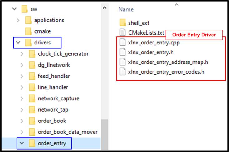
Figure 4‑4 Modified Order entry driver
The Driver Layer of �xlnx_order_entry� is slightly modified from the default AAT software. The modification points are described as follows
1) �xlnx_order_entry_address_map.h�:
· The address variable of IP address and port number are removed and replaced by the TCP session ID.
· The address variable of configuration control and debug status are added.
· The transmission status address value and the read request statistic address value are changed.
2) �xlnx_order_entry.cpp� and �xlnx_order_entry.h�
· �Connect� and �Disconnect� function are modified for controlling the TCP connection by removing TCP session ID instead of IP address and port number.
· �GetConnectionDetails�, �GetTxStatus�, and �GetStats� function which are applied for reading the OrderEntry kernel status are also modified.
· �GetDebugValue� function is added for reading the TCP connection status.
4.2 Shell Object
The shell object of �dg_llnetwork� is implemented for the ease of the application usage. Usability of LL10GEMAC-IP, UDP10GRx-IP inside UDP10GRx16SS, and TOE10GLL-IP inside TOE10GLL32SS, low-layer handling, and friendly user interface are the task of shell object. The modified shell object called �dg_shell_llnetwork� uses �xlnx_shell_ethernet� of the default AAT design as a based reference. The modified shell object has 2 files: C++ source file (dg_shell_llnetwork.cpp) and the header file (dg_shell_llnetwork.h). The header file is similar to the default AAT software while the C++ source file is modified for handling the task. Each command of the C++ source file will be explained later in DG LL-IP shell object topic.
Due to the modification of Line Handler driver and Order Entry driver, the shell object of �xlnx_shell_line_handler� and �xlnx_shell_order_entry� are slightly modified to compatible with the drivers. Moreover, the shell object of the AAT application called �xlnx_aat� is also modified to use the new llnetwork and remove those unused objects such as ethernet, udpip, and tcpip.
4.2.1 DG LL-IP Shell

Figure 4‑5 DG LL-IP Shell
LLNetwork_SetKernelReset and LLNetwork_SetConfigAllowed
The �SetConfigAllowed� command allows user to lock or unlock the driver object. The �SetKernelReset� command asserts or de-asserts the kernel reset. Both commands are the default AAT framework command.
This command allows user to set the source MAC address of UDP10GRx16SS or TOE10GLL32SS depending on the input channel. The input channel parameter is available in Channel#0, #1, or #2 (0: TOE10GLL32SS, 1/2: UDP10GRx16SS). Error is returned if selecting other channels.
This command requires two input parameters, channel number and mac address value. The main software sequences of this command are as follows
1) Verify whether the �dg_llnetwork� driver object is initialized or not. Go to next step if it is initialized.
2) Verify the input parameters whether the inputs are correct or not. Go to next step if they are correct.
3) Call the driver function (SetUDPSourceMACAddress or SetTOESourceMACAddress) to set the source MAC address from the mac address input.
4) The error can be occurred if some sessions are active. To change source MAC address which is common parameters for all sessions in UDP10GRxLL-IP or TOE10GLL-IP, all sessions must not be active.
This command allows user to set the source IP address of UDP10GRx16SS or TOE10GLL32SS depending on the input channel. The input channel parameter is available in Channel#0, #1, or #2 (0: TOE10GLL32SS, 1/2: UDP10GRx16SS). Error is returned if selecting other channels.
This command requires two input parameters, channel number and IP address value. The main software sequences of this command are similar to LLNetwork_SetMACAddress, but driver function (SetUDPSourceIPAddress or SetTOESourceIPAddress) is called to set the source IP address.
This command is used to create a TCP session of TOE10GLL32SS for transmitting the TCP data with respect to its session. To simplify the usability of TOE10GLL32SS, the TCP session is added only one session at a time though TOE10GLL32SS allows user to add multiple sessions at a time. This command can be applied only channel number 0 which includes TOE10GLL32SS and the maximum number of sessions is 32.
This command requires five parameters as follows
1) channel: Channel number to configure
2) ID: Session ID to be created
3) dstipaddr: Destination IP address.
4) dstport: Destination port number
5) srcport: Source port number
The main software sequences of this command are as follows
1) Verify whether the �dg_llnetwork� driver object is initialized or not. Go to next step if it is initialized.
2) Verify all input parameters whether they are correct or not. Go to next step if they are correct.
3) Check if the input TOE session in the specified channel is available. If not available, the error is returned.
4) The inappropriate behavior is found if the parameters of the active session is duplicated. Thus, the functions to confirm the input session parameters is not duplicated with other active sessions are called. The error is returned if the value of the parameter is invalid.
5) Check if there are any sessions use the same destination IP address. If this is the first session using this IP address, this session is assigned to be �Master session�. Otherwise, this session is assigned to be �Slave session�.
6) Call the driver function (SetTOEDestinationMACMode) to set the TOE10GLL-IP initialization mode depends on the session type. The master session is set to initialize by �Client mode� whereas the slave session is set to �Fixed MAC mode�.
7) Call the driver function (SetTOEARPICMPEnable) to set the ARP/ICMP mode. When there is no session enabled, enable this flag. Otherwise, set to disable. This flag is enabled in the first session only to return one ARP/ICMP reply packet.
8) Call the driver function (SetTOETimeoutValue) to set the time out value of all TOE10GLL-IPs when there is no session enabled. Set the value to 3 seconds. This value is loaded by TOE10GLL-IP when the session changes from reset status to active status.
9) Skip this step if the session is Master session. This step is applied to initialize the Save session in �Fixed MAC mode�.
i) Find the session that has the same destination IP address and the status of that session is completely initialized. Error message is returned if it is not found.
ii) Load the destination MAC address from the initialized session and then set to the requested session.
10) Call function to set the session parameters to TOE10GLL-IP inside TOE10GLL32SS. After that, de-assert the session reset of the requested session to �0�.
LLNetwork_DeleteTCPSessionwithID
This command is called by DeleteTCPSession to delete the active session that is requested by assigning channel number and session ID. The main software sequences of this command are as follows
1) Verify that the requested session in the requested channel is enabled. Otherwise, the error is returned by using the driver function (ERROR_TOE_SESSION_INACTIVE).
2) If the requested session is the first opened session and there are other sessions that are still enabled, error is returned (ERROR_FIRST_SESSION_MUST_ACTIVE). The error is found because ARP/ICMP reply must be returned by the first session for the correct operation. Thus, the first session must be the last session that is deleted.
3) Assert the session reset of the requested session inside the requested channel to �1�.
LLNetwork_DeleteTCPSession
This command is used to disable a TCP session of TOE10GLL32SS. Similar to �AddTCPSession� command, this command deletes one session at a time for simple usage. This command requires two input parameters, channel number and session ID to request delete operation.
The main software sequences of this command are as follows
1) Verify whether the �dg_llnetwork� driver object is initialized. Go to next step if it is initialized.
2) Verify all input parameters whether they are correct or not. Go to next step if they are correct.
3) Call DeleteTCPSessionwithID command to delete the session.
This command is used to delete all active TCP sessions by setting the session reset to all �1�. This command requires only one parameter to operate, channel number. The main software sequences of this command are as follows.
1) Verify whether the �dg_llnetwork� driver object is initialized. Go to next step if it is initialized.
2) Verify the input parameter whether it is correct or not. Go to next step if it is correct.
3) Assert all bit of session reset to �1� by calling the driver object function.
This command allows user to set the multicast mode of UDP10GRx16SS which is available in Channel#1 and #2. Error is returned if selecting other channels.
This command requires two input parameters, channel number and the boolean input (�TRUE� to use multicast mode or �FALSE� to use unicast mode). The main software sequences of this command are similar to LLNetwork_SetMACAddress, but driver function (SetUDPMulticastMode) is called to set multicast mode.
This command is used to create a UDP session of UDP10GRx16SS for receiving the UDP data with respect to its session. To simplify the usability of UDP10GRx16SS, the UDP session is added only one session at a time though UDP10GRx16SS allows user to add multiple sessions at a time. Like the other UDP commands, only channel number 1 and 2 contain the UDP block and each channel has 16 sessions at maximum.
This command is required five or six parameters as follows.
1) channel: Channel number to configure
2) ID: Session ID to be created
3) dstipaddr: Destination IP address. The example input format of this parameter is �192.168.100.11�. This parameter is applied when using the unicast mode. In multicast mode, this parameter is ignored.
4) dstport: Destination port number
5) srcport: Source port number
6) mcastaddr (optional): Multicast IP address. The example input format of this parameter is �192.168.100.11�. This parameter is applied when using the multicast mode. In unicast mode, this parameter is ignored.
The main software sequences of this command are as follows
1) Verify whether the �dg_llnetwork� driver object is initialized or not. Go to next step if it is initialized.
2) Verify all input parameters whether they are correct or not. Go to next step if they are correct.
3) Load the multicast mode status from the hardware by using driver function (GetUDPMulticastMode). If the mode is multicast, verify �mcastaddr� input is correct.
4) If all sessions are inactive and the created session is not session#0 - #3, the error is returned. UDP10GRx16SS consists of four UDP10GRx-IPs, one master and three slaves. The master is placed on session#0 - #3. At least one session in the master must be active before allowing some sessions in the slave active.
5) The inappropriate behavior is found if the parameters of the active session is duplicated. Thus, the functions to confirm the input session parameters is not duplicated with other active sessions are called. The error is returned if the value of the parameter is invalid.
6) Call function to set the common parameters and session parameters to UDP10GRx-IP inside UDP10GRx16SS. If it is a multicast mode, set multicast IP address instead of destination IP address. After that, assert the session enable of the requested session to �1�.
LLNetwork_DeleteUDPSessionwithID
This command is called by DeleteUDPSession to delete the active session that is requested by assigning channel number and session ID. The main software sequences of this command are as follows.
1) Verify that the requested session in the requested channel is active. Error is returned if the requested session is not active (ERROR_UDP_SESSION_INACTIVE).
2) If the requested session is the last session of master mode (session#0 - #3) that is active and some sessions of slave mode (session#4 - #15) are still active, the error will be returned (ERROR_UDP_MASTER_SESSION_MUST_ACTIVE). The error is found because the UDP10GRx16SS does not allow to run the slave session without the master session.
3) De-assert the enable flag of the requested session inside the requested channel to �0�.
This command is used to disable a UDP session of UDP10GRx16SS. Similar to �AddUDPSession� command, this command deletes one session at a time for simple usage. This command requires two input parameters, channel number and session ID to request delete operation.
The main software sequences of this command are as follows.
1) Verify whether the �dg_llnetwork� driver object is initialized. Go to next step if it is initialized.
2) Verify all input parameters whether they are correct or not. Go to next step if they are correct.
3) Call DeleteUDPSessionwithID command to delete the session.
This command is used to delete all active UDP sessions by de-asserting session enable to 0. This command requires only one parameter to operate, channel number. The main software sequences of this command are as follows.
1) Verify whether the �dg_llnetwork� driver object is initialized. Go to next step if it is initialized.
2) Verify the input parameter whether it is correct or not. Go to next step if it is correct.
3) De-assert the session enable to �0� by calling the driver object function.
LLNetwork_GetStatus
This command is typically used for checking IP status, network connectivity, network parameters, and error messages. It prints out the common status and the 4-Ethernet channel status. The common status is the details about the kernel index, kernel address, number of Ethernet channels, and kernel reset status. While the 4-Ethernet channel status are the status of LL10GEMAC-IP, UDP10GRx16SS, and TOE10GLL32SS. UDP is available in channel#1-2 and TOE is only available in channel#0.
This command has an optional parameter to specify the Ethernet channel to display the status. Without channel assignment, the status of all channels is displayed. The main software sequences of this command are as follows
1) Verify whether the �dg_llnetwork� driver object is initialized or not. Go to next step if it is initialized. Otherwise, return �ERROR_NOT_INITIALISED�.
2) Verify the input parameters whether the inputs are correct or not. Go to next step if they are correct.
3) Load the common status from the driver object and the hardware. After that, print the common status.
4) If user sets channel parameters, print the channel status following user input. Otherwise, print the status of all channels, starting from channel#0. Channel#0 shows the status of LL10GEMAC-IP and TOE10GLL32SS, Channel#1 and #2 show the status of LL10GEMAC-IP and UDP10G16SS, and Channel#3 shows only the status of LL10GEMAC-IP. The details of the IP status are described as follows.
a) LL10GEMAC-IP status: Ethernet Linkup, EMAC IP version, Tx test pin, and Rx test pin.
b) UDP10G16SS status: UDP10GRx-IP version, test pin, session active, source MAC address, source IP address, and multicast mode which are the shared value for all UDP10GRx-IPs. Next, the parameters of the active session (checked by the session active status) are displayed, i.e., source port number, destination port number, and destination IP address/multicast IP address (multicast IP address when multicast mode=TRUE or destination IP address when multicast mode=FALSE).
c) TOE10GLL32SS status: TOE10GLL-IP version, session active, source MAC address, and source IP address which are the shared value for all TOE10GLL-IPs. Next, the parameters of the active session (checked by the session active status) are displayed, i.e., the connection status, TOE-IP state, destination MAC address, destination IP address, source port number, destination port number, and transmit completed length.
4.2.2 Line Handler Shell

Figure 4‑6 Modified Line handler shell
The shell object of �xlnx_shell_line_handler� is modified from the AAT default software to compatible with the modified hardware. The main modification points in the source file are as follows.
1) The IP address and port number filter parameters are removed from �add� and �delete� command and replaced by the UDP session ID filter parameter. However, the input port and split ID parameter are still utilized.
2) The �GetStatus� command displays the filter parameters table of the input port, UDP session ID, and split ID. The IP address and port number are removed.
4.2.3 Order Entry Shell

Figure 4‑7 Modified OrderEntry shell
Similar to �Line Handler Shell�, the shell object of �xlnx_shell_order_entry� is also modified for hardware compatibility. The main modification points in the source file are as follows.
1) The IP address and port number parameters are removed from �Connect� command and replaced by the TCP session ID parameter instead.
2) The �GetStatus� command displays the TCP session ID instead of the IP address and port number. Also, the TCP connection status is also modified and some status is added to support the TOE10GLL-IP status.
3) The �ConnectionErrorCodeToString� function for generating the error codes is removed.
4.2.4 AAT Shell

Figure 4‑8 Modified AAT shell
�xlnx_shell_aat.cpp� and �xlnx_shell_aat_objects.h� are modified to use the new objects that are replaced the default objects to support the hardware modification. The main modification points in the source file are as follows.
�xlnx_shell_aat_objects.h�: Replace the default included file, xlnx_shell_ethernet.h, by the new included file, dg_shell_llnetwork.h.
�xlnx_shell_aat.cpp�: Update AAT_GetStatusCommand which is applied to list the kernel that is completely initialized. Ethernet, UDPIP0, UDPIP1 and TCPIP object are replaced by a single network object.
4.3 Application Layer

Figure 4‑9 Modified application file
The objective to modify the application layer is to apply the new shell object and drive object with the application software. There are three modified files, i.e., xlnx_aat.h, xlnx_aat.cpp, and main.cpp file. The details of the modification are described as follows.
4.3.1 �xlnx_aat.h�
The modification point in this header is to replace the included header files from xlnx_ethernet.h and xlnx_tcp_udp_ip.h to be the llnetwork header file (dg_llnetwork.h). Also, LLNetwork object is declared instead of Ethernet and TCPUDPIP object.
4.3.2 �xlnx_aat.cpp�
1) Replace the main calling object - ethernet, udpip0, udpip1, and tcpip (the default AAT reference design) by LLNetwork object. The modified driver function is applied, as described in Driver Layer.
2) Modify the �Initialise� function to initialize LLNetwork object instead of ethernet, udpip0, and udpip1 object.
3) Modify the �SetMACAddressesFromNVRAM� function for setting the MAC address of TOE10GLL32SS in channel#0 and UDP10GRx16SS in channel #1 and #2 by using the function of driver object. Also, change the egressing TCP object from channel#1 to be channel#0 for simple mapping table.
4) Modify the �CheckForSufficientMACAddresses� function to match with LLNetwork object specification instead of ethernet object.
4.3.3 �main.cpp�
The modification point in �main� function is the command table object where ethernet, udpip0, udpip1, and tcpip are replaced by network (LLNetwork). The added network object is the shell object of �dg_shell_llnetwork�, as described in Shell Object.
4.4 CMakeList file
The CMakeLists file includes the script for building the software shell application by CMake build system. There are one modified CMakeLists file and two added CMakeLists files in this software architecture. More details of the updated CMakeLists are described as follows.
4.4.1 Modified CMakeLists file

Figure 4‑10 Modified CMakeLists.txt files
There is a CMakeLists file that is modified. The full path of the modified file is at �..sw/applications/aat/CMakeLists.txt�. The modification points of the file are as follows.
· Change the output application name from �aat_shell_exe� to �aat_dgllip_shell_exe�.
· Remove unused driver paths which are ethernet and tcp_udp_ip.
· Add new driver path which is dg_llnetwork.
4.4.2 Added CMakeLists files

Figure 4‑11 Added CMakeLists.txt files
· �..sw/drivers/dg_llnetwork/CMakeLists.txt�: Add the compiled library - �dg_llnetwork�.
· �..sw/drivers/dg_llnetwork/shell_ext/CMakeLists.txt�: Add the shell compiled library.
5 DG LL-IP modification
The DG LL-IP kernel is designed for ease of hardware and software modification to change the number of TCP or UDP sessions to match with the target system requirement. Using less sessions utilizes the less FPGA resource. The hardware modification of DG LL-IP kernel does not require the FPGA expertise though the DG LL-IP kernel is coded in low-level language. To update the feature, the software should be updated after the hardware updated for the compatibility.
Hardware modification
The top file of �dg_llip_kernel� hardware called �dg_llip_kernel.vhd� is written in VHDL language, as shown in Figure 5‑1. In HDL code, the default number of TCP and UDP sessions are 32 and 16 sessions, respectively. To update number of sessions, it can be done by changing the integer value of the cNUMTOESS for the number of TCP sessions and the cNUMUDPSS for the number of UDP sessions. Figure 5‑1 shows the example to change the number of TCP and UDP sessions to 4 sessions for both TCP and UDP.
The range of TCP sessions and UDP sessions in this design are 1-32 and 1-16, respectively. After updating the design, the DG LL-IP kernel hardware must be re-built and the xclbin must be re-generated.

Figure 5‑1 Modify number of sessions in hardware
Software modification
After the DG LL-IP kernel hardware is modified to change the number of TCP or UDP sessions, the software needs to update for hardware compatibility. Similar to the hardware design, the software is also written for ease of adjustment. To change the number of available TCP or UDP sessions in software, only the �dg_llnetwork.h� file in driver directory is needed to updated, as shown in Figure 5‑2. The left-hand side of Figure 5‑2 shows the default number of TCP and UDP session, 32 and 16 sessions, respectively. While the right-hand side of Figure 5‑2 shows the updated number of available TCP and UDP sessions - 4 sessions for both TCP and UDP.
Similar to the Hardware modification, the range of TCP sessions and UDP sessions are 1-32 and 1-16, respectively. After updating the software code, the software application �aat_dgllip_shell_exe� must be re-built.

Figure 5‑2 Modify number of sessions in software
Table 5‑1 shows the resource utilization of DG LL-IP kernel on Alveo U250 card when using the default design (32 TCP sessions and 16 UDP sessions) and using the modified design (4 TCP sessions and 4 UDP sessions). The resource is reduced when using less sessions. Thus, it is recommended user to adjust the number of sessions to match with the system requirement.
Table 5‑1 DG LL-IP kernel resource utilization
|
Design |
Example Device |
CLB Regs |
CLB LUTs |
CLB |
BRAMTile |
Design Tools |
|
Default DG LL-IP - TCP 32 sessions - UDP 16 sessions |
Alveo U250 |
148919 |
131062 |
24934 |
51 |
Vitis2022.1 |
|
Modified DG LL-IP - TCP 4 sessions - UDP 4 sessions |
Alveo U250 |
30383 |
25611 |
5384 |
9 |
Vitis2022.1 |
6 Revision History
|
Revision |
Date |
Description |
|
2.0 |
14-Jul-22 |
Add TOE10GLL IP |
|
1.0 |
4-Jan-22 |
Initial version release |