
Design Gateway Co., Ltd
E-mail: ip-sales@design-gateway.com
URL: design-gateway.com
Features
· Comprehensive TCP/IP offloading engine
· Support IPv4 protocol without IP fragmentation
· Support up to 4 TCP sessions connected to the same remote target
· Support Jumbo frame
· Configurable TCP buffer size: Up to 1 MB
· User data interface: 1024-bit AXI4-ST interface with configurable data alignment
· Configurable data alignment options: Byte alignment (8-bit) or 128-byte alignment (1024-bit)
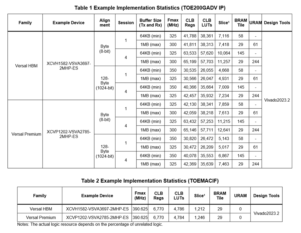
· Recommended operating clock frequency: At least 250 MHz
· Ethernet MAC interface: 1024-bit AXI4-ST interface with a provided adapter IP core, TOEMACIF, for seamless integration with AMD Ethernet Subsystem
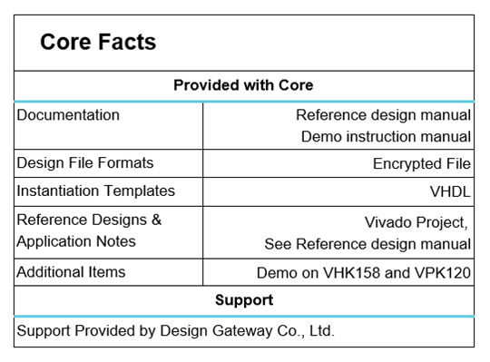
· Reference designs available for the VHK158 and VPK120 boards
· Customized options available for:
· Additional buffer sizes
· Specified number of TCP sessions
· Ping command support
Applications
The TOE200GADV IP core serves as a full TCP/IP offloading engine and does not require a CPU or external memory for TCP/IP packet processing. This IP allows for the seamless transmission of TCP/IP packets at the full 200G Ethernet line rate.
Figure 1 illustrates an example of TOE200GADV IP core integration with an FPGA Network Interface Card, serving as a high-performance TCP Accelerator engine for managing four concurrent TCP sessions.

Figure 1 TCP Accelerator System
Within the Host System, the host processor takes on the responsibility of selecting four performance-sensitive TCP sessions, handled by the TOE200GADV IP. Concurrently, the host processor processes the remaining Ethernet packets via the Host2MAC module to support the remaining TCP sessions and other protocols that do not require high-performance handling. User data processed by TOE200GADV IP is directly transferred to the Host memory by the DMA engine, allowing applications running on the host processor to access this data.
In contrast, other Ethernet packets transferred through the Host2MAC module are stored separately within the host memory, awaiting the host processor decoding before they can be utilized by the applications. The incorporation of the TOE200GADV IP core significantly enhances the performance of TCP data transfer within the network interface application.
As illustrated in Figure 2, another application scenario for TOE200GADV IP revolves around the utilization of an FPGA card to implement NVMe/TCP Initiator system.

Figure 2 NVMe/TCP Initiator System
The NVMe/TCP protocol facilitates remote access to storage systems equipped with NVMe SSDs through network connectivity. Each NVMe/TCP connection is associated with either an Admin Queue or an I/O Queue. Therefore, multiple TCP connections are used to handle Admin and I/O commands separately. In this example, each NVMe controller uses one TCP connection for the Admin Queue and one TCP connection for an I/O Queue, allowing multiple NVMe SSDs to be accessed through multiple TCP connections.
The TOE200GADV IP core can concurrently handle up to four TCP sessions. Consequently, in this example, the Initiator logic can concurrently access two NVMe SSDs installed in the remote target system, using two TCP connections for each SSD. By offloading TCP/IP processing to the TOE200GADV IP, the NVMe/TCP Initiator logic does not need to implement the TCP/IP stack and can focus on NVMe/TCP protocol and NVMe command processing. A fully hardware-based implementation enables high-performance data transfer, making it suitable for applications such as real-time transmission of high-resolution video data to remote storage.
General Description

Figure 3 TOE200GADV IP Block Diagram
The TOE200GADV IP core is a complete TCP/IP offload engine designed to process TCP/IP packets in high-speed Ethernet systems. It provides individual Tx and Rx user data interfaces for up to four TCP sessions, with a common Control I/F. Most network parameters are shared across all sessions, while the TCP port number can be configured independently for each session. In addition, the transmit and receive TCP buffer sizes for each TCP session can be configured independently to match the specific requirements of each connection.
For Ethernet packet transfer, the TOE200GADV IP uses a 1024-bit AXI4-ST interface to communicate with the Ethernet Subsystem through the TOEMACIF module, which operates as adapter logic between the TOE200GADV IP and the Ethernet MAC interface. The internal logic of the TOE200GADV IP is divided into three main blocks: the Control block, the Transmit block, and the Receive block.
The Control block is connected to the Control I/F of the user interface. It is responsible for command configuration, network parameter management, and IP status monitoring. Within the Control block, the MainCtrl component receives user command requests and stores associated user parameters in Param Regs. After validating the command, MainCtrl generates a command request for the respective TCP engine. The system incorporates four TCP engines, each dedicated to managing the operations of individual TCP sessions.
The Transmit block manages the TCPTx I/F, facilitating the transmission of TCP payload data through a 1024-bit AXI4-ST I/F. When byte-level data alignment is configured, data received from the user interface is re-aligned before being stored in the TxTCP buffer. When 128-byte data alignment is selected, the data aligner is not required because the user data is already aligned to the 1024-bit interface width.
When the user requests data transmission, the Packet Builder retrieves payload data from the TxTCP buffer and constructs TCP/IP packets. The completed packets are then transferred to the TOEMACIF module for transmission through the Ethernet MAC.
The Receive block manages the TCPRx interface and receives TCP/IP packets from the Ethernet Subsystem through a 1024-bit AXI4-ST I/F. Its operation is generally the reverse of the Transmit block. Incoming packets are validated by the Packet Filtering logic, and the TCP payload data extracted from valid packets is stored in the RxTCP buffer. When data is available in the RxTCP buffer and the user is ready to receive it, the data is transferred directly to the user if 128-byte data alignment is selected. If byte-level data alignment is configured, the RxAligner re-aligns the received data before forwarding it to the user interface.
Design Gateway also includes the TOEMACIF module as an encrypted file in the TOE200GADV IP core release package. This module serves as an adapter logic, bridging the connection between the Ethernet MAC interface of TOE200GADV IP (1024-bit AXI4-ST I/F) and the user interface of the Ethernet Subsystem (512-bit Segmented AXI4-ST I/F of DCMAC on Versal device). Due to the Ethernet Subsystem’s operation in a distinct clock domain (MACClk) from the user logic, TOEMACIF incorporates two asynchronous buffers in the Transmit block and Receive block, namely the TxMAC buffer and the RxMAC buffer, to facilitate data streaming across clock domains.
For additional details about each submodule within the TOE200GADV IP and TOEMACIF, please refer to the following section.
Functional Description
The TOE200GADV IP has two sets of functions: common functions, which are employed for every TCP session, and session-specific functions that operate within each session. The common functions facilitate communication with the remote target device, while the session functions are responsible for managing individual TCP sessions, as illustrated in Figure 4.

Figure 4 TOE200GADV IP Functional Diagram
Common States
1) Reset: When the TOE200GADV IP is powered-on, the default state is Reset. This state is designed to wait for the user to configure network parameters for both the local host and the remote target, including MAC address and IP address. Once all parameters, including the initialization mode (DstMacMode), are set, the user can de-assert RstB to 1b to initiate the target’s initialization.
2) Target Initialization: This state is used to obtain the MAC address of the target and store the user-assigned network parameters in internal registers. There are three modes, determined by DstMacMode, for acquiring the remote target’s MAC address: Client (generating ARP request packet), Server (waiting for ARP request packet), and Fixed-MAC (user-defined value). Once the target’s MAC address is successfully obtained, the initialization process is completed, and the TOE200GADV IP is ready to establish a connection with the target.
3) Target Ready: After successful target initialization, the main function remains in this state until a reset is asserted. In this state, the user can send command request specifying the active session (Session#0-Session#3) and the operation (Open, Close, and Reset) to be performed by the main function. If the operation request is invalid, such as sending a Close request to an inactive session, the main function will reject the request. Valid requests are forwarded to the session-specific function, which returns either a completion or an error status to the main function after executing the operation.
Additionally, it is important to note that the session’s status may also change without any request from the main function if the remote target device sends a request to open, close, or reset the session.
Session States
1) Session Inactive: Following a reset, each session function enters the Inactive state. In this state, the session function awaits an open session request from the main function (active open) or the remote target device (passive open). Session establishment is initiated upon receiving the open session request.
2) Create Session: Session creation involves a three-way handshake process using SYN, SYN-ACK, and ACK packets. The first SYN packet can be sent by either the TOE200GADV IP (active open) or the target (passive open). Another device responds with a SYN-ACK packet if it accepts the connection request. Finally, the process is completed when the first device that initiated the SYN packet sends an ACK packet. Once the connection is successfully established, it becomes ready for data transfer, and the session function reports its status upon completing this process.
3) Session Ready: The TCP protocol facilitates bidirectional data transfer, allowing simultaneous transmission and reception of data within the same session. This is achieved by assigning unique sequence and acknowledgement numbers for each data transfer direction to indicate the position of transmitted and accepted data. However, Figure 4 illustrates the separate representation of ‘Send data’ and ‘Receive data’ to show the fundamental concept of the TOE200GADV IP’s functionality.
4) Send Data: Each session possesses its dedicated data interface, compatible with a 1024-bit AXI4-ST interface, designed for transmitting data to the target. However, TOE200GADV IP permits only one session to transmit packets at a time. Each session includes a TxTCP buffer for storing data transmitted by the user. The sequence number of the transmitted packet is updated after data is sent from the TxTCP buffer to the target. The data is removed from the buffer once the target updates the acknowledgement number to confirm the amount of received data. If all data is successfully transmitted, the session state returns to the ‘Ready’ state. If the session is terminated, the TxTCP buffer is automatically flushed.
5) Receive Data: Each session includes an RxTCP buffer for storing data received from the remote target. In accordance with the TCP protocol, the available space in the RxTCP buffer is reflected in the TCP receive-window value advertised by the TOE200GADV-IP in packets transmitted to the target. Consequently, the target can continuously send data to TOE200GADV IP without waiting for an updated acknowledgement number until the amount of unacknowledged data reaches the window size limit.
While receiving data, the sequence number of received packet is monitored to ensure the correctness of the received data sequence. If any received data is lost during this process, the TOE200GADV IP generates duplicate ACK packets to request packet retransmission. After the received data is stored to the RxTCP buffer, the TOE200GADV IP updates the acknowledgement number and generates a packet, confirming that the received data has been accepted.
The RxTCP buffer is automatically cleared during the session establishment process. The user can read data from the RxTCP buffer through the 1024-bit AXI4-ST interface provided for each session individually, allowing data to be read from multiple sessions simultaneously.
6) Terminate Session: Session can be terminated either by the TOE200GADV IP (active close) or the remote target (passive close). The first packet used to initiate connection termination is the FIN packet. If the termination request is accepted by another device, it responds with FIN and ACK packets, which can be transmitted in a single packet or multiple packets. Finally, the initiating device sends an ACK packet to complete the process. Upon the successful termination, the session function transitions back to the Inactive state. The session function provides a status update upon the completion of this termination process.
The hardware modules are organized into three distinct blocks: Control, Transmit, and Receive. Each block is responsible for specific functions, as outlined below.
Control Block
· MainCtrl
The main controller, known as MainCtrl, involves the main functions (common block in Figure 4), which were elaborated upon in the preceding section: Reset, Target initialization, and Target Ready. It decodes the user-assigned commands and parameters to determine the subsequent processes.
For instance, it manages distinct sequences for transmitting and receiving packets to accommodate three types of initialization processes. It generates various request types for the transmit and receive blocks, facilitating the creation or interpretation of ARP request and ARP reply packets. Once the MAC address of the remote target is acquired, the result is stored in Param Regs for utilization by other submodules.
In scenarios where a user’s command cannot be supported under specific conditions, the main controller will reject the command and issue an error status.
· Param Regs
The parameters stored at Param Regs can be received from the local user assignment or retrieved from the receive block. The local user-defined parameters include both the local host and the remote target parameters such as the MAC address, the IP address, and the port number. Parameters decoded by the receive block include remote target parameters such as the MAC address and port number, which are used under specific conditions.
Furthermore, various configuration parameters, including timeout values, initialization mode, initial Maximum Segment Size (MSS), and threshold values, are also assigned by the local user and stored within Param Regs for utilization by the main controller.
· TCP Engine
The TCP Engine manages the operations of each individual TCP session, as described in the session-specific functions shown in Figure 4.
The establishment of a connection can be triggered by either of two devices. In active open mode, the TCP engine prompts the transmit block to send SYN and ACK packets while instructing the receive block to validate a SYN-ACK packet. Conversely, for passive open mode, the packet types of the transmit block and the receive block are reversed.
To send data, once the amount of data in the TxTCP buffer reaches a certain threshold, the TCP engine calculates the sequence number for the transmitted packet. It instructs the transmit block to continuously send data until the total amount of transmitted data reaches the designated value, determined from the latest target window size retrieved by the receive block. The TCP engine will pause the transmit block if the window size and acknowledgement number from the remote target are not updated. In cases of lost transmitted data, which is indicated by the generation of duplicate ACK packets by the target, the TCP Engine will suspend the operation of the transmit block and generate the new parameter sets to initiate data retransmission through the transmit block. TOE200GADV IP provides a status signal indicating the remaining amount of transmitted data yet to be received by the remote target, allowing the local user to monitor the progress of the transmission operation. The send operation is considered completed when there is no remaining transmitted data in the TxTCP buffer.
To receive data, the TCP engine continuously monitors the sequence number of the received packet, retrieved from the receive block. This information is used to calculate the quantity of received data. When the received data reaches a specified threshold, the TCP engine computes the acknowledgement number and configures it to the transmit block. This action triggers the sending of a packet, which serves to update the current values of acknowledgement number and the window size of the RxTCP buffer. If the sequence number of a received packet is skipped, it indicates a data loss situation. In such cases, the TCP engine instructs the transmit block to generate duplicate ACK packets for the recovery of the missing data.
When operating in receive-only mode, the local user can configure how quickly the TCP engine triggers the transmit block for sending an ACK packet. This feature allows tuning of ACK packet frequency, helping to avoid excessive or overly frequent ACK packet transmission that might unnecessarily consume the network bandwidth.
Additionally, the TCP engine offers the local user the flexibility to define a threshold value for generating TCP window update packets. This feature is useful when the user logic stops reading data from the RxTCP buffer until it is full. During this period, the target cannot send more data to this session.
However, once the user resumes data reading and the free space within the RxTCP buffer increases to the specified threshold value, the TCP engine instructs the transmit block to send an ACK packet, updating the TCP window size based on the RxTCP buffer’s free space. Then, the target can resume data transmission.
The connection termination can be done by either of two devices. In active close mode, the TCP engine prompts the transmit block to send FIN and ACK packets while instructing the receive block to validate FIN and ACK packets. Conversely, for passive close mode, the packet types of the transmit block and the receive block are swapped.
Transmit Block
· Tx Aligner
This module is included only when the data alignment option is configured as byte alignment, or 8-bit alignment. In this mode, the user logic transfers data to the TOE200GADV IP through a 1024-bit AXI4-ST interface. All bytes in each 1024-bit data beat are valid, except for the final data beat of a transfer. For the final data beat, the ‘keep’ signal indicates which bytes contain valid data.
Therefore, TxAligner is responsible for realigning the next transmitted data when the previous transfer does not end on a 1024-bit boundary. One TxAligner module is shared among all four user transmit data interfaces, so only one user interface can transfer data at a time. Since the same Ethernet MAC is shared by all four TCP sessions, one active user transmit interface provides sufficient bandwidth to achieve the maximum 200G Ethernet performance. The realigned data from TxAligner is then stored in one of the four TxTCP buffers, depending on the active user number.
When the data alignment option is configured as 128-byte alignment, or 1024-bit alignment, this module is bypassed. In this mode, the 1024-bit user data is stored directly in the corresponding TxTCP buffer.
· TxTCP Buffer
The TxTCP buffer serves as the buffer for transmitted data from the user in each TCP session. The size of this buffer is configurable through the parameter ‘TxBufBitWidth<i>’, where ‘i’ corresponds to the session number (ranging from 0 to 3). A mapping table to show the relationship between ‘TxBufBitWidth’ and the actual size of TxTCP buffer is provided in Table 3.
Table 3 TxBufBitWidth and RxBufBitWidth Parameter Description
|
Configuration value |
Buffer size |
|
9 |
64 KB |
|
10 |
128 KB |
|
11 |
256 KB |
|
12 |
512 KB |
|
13 |
1 MB |
The maximum data payload size of each transmitted packet is constrained by the negotiated MSS value, which is determined during the connection establishment process. If the amount of transmitted data exceeds this limitation, the data must be divided and transmitted across multiple packets. Each segmented payload data for each TCP packet is then sent to the Packet Builder to construct complete TCP packets.
The transmitted data remains stored in the TxTCP buffer until the TCP Engine confirms that the data has been received by the target. Consequently, having a large TxTCP buffer size allows for continuous data transmission to the target without waiting for updated ACK packets from the target for extended periods. If the target finishes processing the received data and issues an ACK packet before the TxTCP buffer reaches its capacity, data can be transmitted without pauses, enabling the achievement of the maximum data rate of 200G Ethernet. However, it is essential to note that this advantage does come at the cost of significant FPGA memory resources.
· Packet Builder
To encapsulate TCP payload data within an Ethernet packet, various layers of header data must be appended, including parameters such as MAC addresses, IP addresses, port numbers, sequence number, acknowledgement number, window size, TCP flags, and checksums. This module is responsible for computing the checksums for both the TCP and IP layers and substituting these calculated values into the packet header. Once the header is fully assembled, it is merged with the segmented payload data obtained from the TxTCP buffer before being transmitted to the TOEMACIF.
In addition to creating TCP/IP packets, the packet builder must also support generating ARP request and ARP reply packets, which may be required during the IP initialization process.
Since the Packet Builder is shared among four TCP sessions, it must be capable of switching the active TCP session after transmitting a packet for one session to handle packets for the remaining sessions once their data is ready for transmission.
Receive Block
· RxPac Buffer
TOEMACIF can transmit Ethernet packets to TOE200GADV IP at any time, whereas the TOE200GADV IP requires a short pause time while processing each Ethernet packet. Consequently, the RxPac buffer must be included for storing Ethernet packets when the receive logic of TOE200GADV IP are not ready to accept new data. In specific scenarios, the RxPac buffer may become full, leading to the incomplete storage of incoming packets. As a result, the interrupt is asserted by TOE200GADV IP at TOEMACRx I/F to signal that the most recent packet has been discarded. However, if TCP engine detects the loss of a packet, it will initiate a data retransmission process to recover the missing packets. Increasing the frequency of the user logic’s clock domain (Clk) decreases the likelihood of the RxPac buffer reaching full capacity.
Note: The required clock frequency for user logic (Clk) to ensure lossless packet reception in the RxPac buffer can be approximately estimated as follows:
Assume a 1536-byte TCP payload is received continuously from the Ethernet MAC without any pauses. The TOE200GADV IP requires 13 clock cycles for packet reception and an additional 3 clock cycles for pause time. Meanwhile, the Ethernet MAC transfers data using approximately 12.5 clock cycles. The user logic clock frequency without RxPac buffer overflow should be:
Clk = (13+3)/12.5 x 195.3125 MHz = 250 MHz.
· Packet Filtering
This module is responsible for validating incoming packets. To be considered valid, a packet must meet the following criteria.
1) Network parameters, such as MAC address, IP address, and Port number, must match the local user-defined settings established during initialization.
2) The packet must be either an ARP packet or an unfragmented TCP/IPv4 packet.
3) The IP header length must be 20 bytes, and the TCP header length must be within the range of 20 to 60 bytes.
4) Both the IP checksum and TCP checksum must be correct.
5) The data pointer, as determined by the sequence number, must be within a valid range.
6) The acknowledge number must also be within an acceptable range.
7) Time To Live (TTL) must not be equal to 0.
If a packet meets these validation criteria and contains TCP payload data, the Packet Filtering will extract the TCP payload data and store it in the appropriate RxTCP buffer, determined by the port number value. After the received packet has been fully processed, a signal is generated to notify the TCP Engine to update the current status. In specific scenarios, the TCP Engine may request the Transmit block to generate a packet with updated information, such as acknowledge number and window size, for transmission to the target.
· RxTCP Buffer
The RxTCP buffer serves as the buffer for received TCP payload data from the remote target in each TCP session. Its size is configurable through the parameter ‘RxBufBitWidth<i>’, where ‘i’ corresponds to the session number (ranging from 0 to 3). Table 3 provides a mapping table to show the relationship between ‘RxBufBitWidth’ and the actual size of RxTCP buffer.
Data received from the target remains stored in the RxTCP buffer until the user reads it via the 1024-bit AXI4-ST I/F. The target continues to transmit TCP payload data until the RxTCP buffer becomes full. Therefore, using a larger RxTCP buffer size increases the chance that the target can continuously send data to the TOE200GADV IP without a pause if the user consistently reads data to free the buffer during operation. As a result, peak performance can be achieved. Besides, the TCP Engine utilizes the remaining space of RxTCP buffer as the TCP window size in transmitted packets when it needs to update information to the target.
· Rx Aligner
This module is included only when the data alignment option is configured as byte alignment, or 8-bit alignment. In this mode, 1024-bit data from the RxTCP buffer can be transferred directly to the user logic for each full data beat. However, the final data beat of a received packet may contain only a partial number of valid bytes. When this final beat is not aligned to the 1024-bit boundary, the next received data output from the RxTCP buffer must be realigned by the RxAligner before being forwarded to the user logic.
To support this operation, the subsequent data remains in an unaligned state internally, and the last-beat flag is used to control the realignment process. The RxAligner then realigns the 1024-bit data output from the RxTCP buffer to match the 1024-bit AXI4-ST interface of the user logic. This restores the data stream to the correct alignment after an unaligned transfer. More details of the Rx alignment function are provided in Figure 25.
When the data alignment option is configured as 128-byte alignment, or 1024-bit alignment, this module is bypassed. In this mode, the 1024-bit data output from the corresponding RxTCP buffer is transferred directly to the user logic through the 1024-bit AXI4-ST interface.
TOEMACIF
· TxMAC Buffer and RxMAC Buffer
TxMAC and RxMAC buffers are asynchronous buffers integrated into the Transmit and the Receive blocks. They perform clock-domain crossing for the data stream between the user clock domain (Clk) and the Ethernet Subsystem clock domain (MACClk).
· TxMAC Adapter and RxMAC Adapter
The TxMAC and RxMAC adapter logic are designed to convert data stream format between AXI4-ST interface and Segmented AXI4-ST interface. Additional details about the Tx and Rx Segmented AXI4-ST interfaces can be found on the AMD website.
https://docs.amd.com/r/en-US/pg369-dcmac/Transmit-Segmented-AXI4-Stream
https://docs.amd.com/r/en-US/pg369-dcmac/Receive-Segmented-AXI4-Stream
User Logic
As illustrated in Figure 3, the user logic is responsible for managing three distinct user interfaces of the TOE200GADV IP. These interfaces include the Control I/F, utilized for network and system parameter configuration and status monitoring; the TCPTx I/F, designed for data transmission; and the TCPRx I/F, intended for the reception of data streams.
Network and system parameters for the TOE200GADV IP, such as timeout values, can be set using constant values or user-defined registers. Furthermore, overseeing the signals responsible for initiating command requests and monitoring operational status can be achieved through a state machine. This approach facilitates the customization of command values and enables real-time tracking of operations, including error detection.
Both the Tx and Rx data interfaces employ a 1024-bit AXI4-ST bus interface. This design choice offers users flexibility, enabling them to map the data interface of the TOE200GADV IP to other components that are compatible with the AXI4-ST bus. This facilitates efficient data handling and processing.
600G Multirate Ethernet Subsystem
The AMD Versal 600G Channelized Multirate Ethernet Subsystem (DCMAC) implements the Ethernet MAC and lower-layer PCS functions according to its configured operating mode. In TOE200GADV IP reference designs, the Ethernet Subsystem has been configured with the following parameters.
- DCMAC Operating Mode : Coupled MAC + PCS
- AXIS Datapath Interface : 391 MHz Up to 6 Ports
- MAC Port0 : Enable and Tx FCS Insert
- MAC Port1-5 : Disable
- Default PCS Mode : 200GAUI-4
For additional details regarding this IP, please visit the following website:
https://www.amd.com/en/products/adaptive-socs-and-fpgas/intellectual-property/dcmac.html
Core I/O Signals of TOE200GADV IP
Table 4 provides detailed descriptions of configurable parameters, while Table 5 outlines the I/O signals for TOE200GADV IP. The TOEMAC interface matches the 1024-bit AXI4-ST standard.
Table 4 Core Parameters
|
Name |
Value |
Description |
|
ByteAlignEn |
1 or 0 |
Configure the data alignment mode for the TCPTx I/F and TCPRx I/F, both of which use a 1024-bit AXI4-ST I/F. 1: byte alignment, 0: 128-byte alignment. |
|
NumberSession |
1 – 4 |
Set the number of TCP sessions |
|
TxBufBitWidth0-3 |
9 – 13 |
Set TxTCP buffer size. Table 3 shows the relation between this value and the actual size. |
|
RxBufBitWidth0-3 |
9 – 13 |
Set RxTCP buffer size. Table 3 shows the relation between this value and the actual size. |
Table 5 User I/O Signals
|
Signal name |
Dir |
Description |
|
User Control Interface (Common) |
||
|
RstB |
In |
Reset IP core. Active Low. Once RstB changes to 1b, the IP initiates the initialization process. Note: Before de-asserting RstB to 1b, the values of DstMacMode, SrcMacAddr, DstMacAddrIn (if used), SrcIPAddr, DstIPAddr, WindowThres, MSSInitValSet, TCPCtlTimeOutSet, TCPRxTimeOutSet, and TCPAckDlyTimeSet must be stable. Also, these values must be sustained for 4 clock cycles after the de-assertion of RstB. |
|
Clk |
In |
User clock. Recommended to set a clock frequency of at least 250 MHz to minimize the chance of RxPac buffer overflow. |
|
IPVersion[31:0] |
Out |
Represents the IP version number. |
|
TestPin[63:0] |
Out |
Reserved to be the IP test point. |
|
DstMacMode[1:0] |
In |
Defines the options for obtaining the MAC address of the target, with additional details provided in Figure 5 – Figure 7. 00b – Client mode. In this mode, the IP generates an ARP request packet during IP initialization, and the remote target MAC address is extracted from the received ARP reply packet. 01b – Server mode. In this mode, the IP awaits an incoming ARP request packet during IP initialization, and the remote target MAC address is extracted from the received ARP request packet. 1Xb – Fixed-MAC mode. This mode allows the user to specify the target MAC address using the ‘DstMacAddrIn’ value, assigned by the user. Note: When the local host and remote target are located on different networks, the ‘Fixed-MAC’ mode must be utilized. In such cases, the ’DstMacAddrIn’ value should be set to the gateway’s MAC address. |
|
SrcMacAddr[47:0] |
In |
Defines the local host MAC address. |
|
DstMacAddrIn[47:0] |
In |
Defines the remote target MAC address, used in Fixed-MAC mode. |
|
DstMacAddrOut[47:0] |
Out |
Displays the remote target MAC address. Valid after InitFinish is set to 1b (IP initialization is completed). |
|
SrcIPAddr[31:0] |
In |
Defines the local host IP address. |
|
DstIPAddr[31:0] |
In |
Defines the remote target IP address. |
|
WindowThres[9:0] |
In |
Defines the threshold value, measured in 1KB units, to determine when the ‘TCP Window Update’ packet is sent to the target. It is valid within the range of 0 to 1023. The default value is 0, indicating that this feature is disabled. It becomes enabled when other values are set. It is recommended to be configured to one-fourth of the RxTCP buffer size. During receiving data from the target, the IP generates ACK packets containing the TCP window size. If the remaining TCP window size is insufficient, the target temporarily halts data transmission until the TCP window size increases. Once the user reads data and the available free space in the RxTCP buffer reaches or exceeds this threshold, the IP transmits a ‘TCP Window Update’ packet to update the TCP window size. Upon detecting adequate free space, the target resumes transmitting the next data. |
|
MSSInitValSet[13:0] |
In |
Define the initial Maximum Segment Size (MSS) in bytes for TCP communication, with a configurable range from 536 to 8960. The defined value is applied for all TCP sessions during connection establishment to negotiate the final MSS with the target device. Each session of TOE200GADV IP individually determines the negotiated MSS from the smaller value between the target device’s MSS and the local MSSInitValSet set by the user. The final negotiated MSS value of a specific TCP session can be found in TCPConnStatus after the connection is established. |
|
TCPCtlTimeOutSet[31:0] |
In |
Defines timeout value, ranging from 1 to FFFF_FFFFh. The timer operates in sync with the ‘Clk’ signal, with a time unit equivalent to the ‘Clk’ signal’s time period (4 ns for 250 MHz). It counts while awaiting returned packets from the target during each operation. When a timeout occurs, the IP asserts ‘TCPRtrInt’ for recoverable conditions or ‘TCPRstInt’ for conditions requiring connection termination. The corresponding status signal (TCPRtrIntStatus or TCPRstIntStatus) identifies the timeout condition. The optimal value depends on system requirements and network characteristics, but it is typically set to 1 second or larger. An example of its usage is presented in Figure 30. |
|
TCPRxTimeOutSet[23:0] |
In |
This signal is unused when ByteAlignEn=0, which selects the 128-byte alignment configuration. When ByteAlignEn=1, this signal sets the timeout value for byte-alignment mode. Similar to ‘TCPCtlTimeOutSet’, the timeout operates in sync with the ‘Clk’ signal. Its value ranges from 1 to FF_FFFFh. The same timeout value is applied for all TCP sessions. This timer counts when the RxTCP buffer holds the last unaligned data (not 1024 bits). When a timeout is triggered, the TOE200GADV IP flushes the last data to the user via TCPRx I/F, with ‘TOERxLast<i>’ asserted to 1b. The optimal value depends on the pause time of the target for transmitting data. An example of its usage is presented in Figure 25. |
|
Signal name |
Dir |
Description |
|
User Control Interface (Common) |
||
|
TCPAckDlyTimeSet[9:0] |
In |
Defines the ACK delay timeout value. Similar to ‘TCPCtlTimeOutSet’, the timeout operates in sync with the ‘Clk’ signal and ranges from 1 to 1023. The same timeout value is applied for all TCP sessions. This timer counts when the TCP Engine realizes there is newly received data stored to RxTCP buffer. Upon timeout, the transmit block is triggered to send an ACK packet back to the target device with the updated acknowledgment number. This delay operation is active only when the TCP session does not have any TCP payload data to transmit. The optimal value depends on system requirements and network characteristics, but it is typically set to 128 cycles or larger to avoid unnecessary ACK packet transmission. An example of its usage is presented in Figure 28 and Figure 29. |
|
InitFinish |
Out |
Represents the completion status of IP initialization process. It is set to 0b when the IP is reset and changes to 1b once the initialization process is completed. |
|
User Control Interface (Session) |
||
|
TCPConnCmd[3:0] |
In |
Defines the command value corresponding to the requested session. [1:0] – Command 00b: Active open. The IP initiates connection establishment by sending a SYN packet. 01b: Passive open. The IP waits for the target to initiate connection establishment. Note: Active open and Passive open commands can be issued when ‘InitFinish’=1b, ‘TCPConnOn[i]’=0b, and ‘TCPConnStatus[(64*i)+4]’=0b, where ‘i’ represents the session number defined by ‘TCPConnCmd[3:2]’. Once a connection is established successfully, ‘TCPConnOn[i]’ changes to 1b. 10b: Active close. The IP initiates connection termination by sending a FIN packet. This command should be issued when ‘TCPConnOn[i]’=1b, where ‘i’ is session number, and there is no remaining data stored in TxTCP buffer for that session. 11b: Reset. This command allows the user to reset only specified session without interrupting the operation of other sessions to recover from unusual conditions. [3:2] – Session number to request the command. 00b: Session#0, 01b: Session#1, 10b: Session#2, and 11b: Session#3. Additional information on how to utilize TCPConnCmd is illustrated in Figure 8 – Figure 17. |
|
TCPSrcPort[15:0] |
In |
Defines the local host port number. |
|
TCPDstPort[15:0] |
In |
Defines the remote target port number. This value is not used if operating Passive open. |
|
TCPLastMode[1:0] |
In |
Configures the last transmission mode to determine how the last packet is sent to accelerate the target’s response. Reducing response time can enhance transfer performance. 00b – Duplicated data. The IP sends the last packet twice, causing the target to recognize the second packet as a retransmission. Consequently, the target responds with an acknowledgement packet, thereby completing the data transfer from the local host. 1Xb - PSH flag. The IP sets the PSH flag in the TCP header. The PSH flag requests that the receiving TCP stack promptly make the received data available to the application. This may reduce response latency of ACK packet generating from the remote target. 01b – Normal packet (No PSH or Duplicate packet). In this mode, a standard packet is generated without any additional setting to accelerate the remote target’s response. Figure 21 and Figure 22 provide the details of the configuration for the last transmission mode. |
|
TCPConnReq |
In |
Sets this signal to 1b for a single clock cycle to initiate a command request when ‘TCPConnReady’=1b. During this time, ‘TCPConnCmd’ must contain valid data. Additionally, while setting this signal to 1b and assigning ‘TCPConnCmd’ as Active open or Passive open, ‘TCPSrcPort’, ‘TCPDstPort’ (only used for Active open), and ‘TCPLastMode’ are loaded. |
|
TCPConnReady |
Out |
Sets to 1b when the IP is ready to accept the new command. Once ‘TCPConnReq’ is set to 1b, this signal is then de-asserted to 0b for 2 clock cycles to prevent any further command requests. |
|
TCPConnCpl |
Out |
Sets to 1b for a single clock cycle to signal the completion of a command operation. The status of the command completion is conveyed through ‘TCPConnCplStatus’. |
|
TCPConnCplStatus[4:0] |
Out |
Represents the command completion status. Bits[3:0] identify the command status (completed or error) and match TCPConnCmd[3:0]. Bit[4] indicates the completion result: 0b: Fail, 1b: Success. |
|
TCPConnOn[3:0] |
Out |
Represents the active status of individual TCP sessions, with each bit corresponding to a specific session. Bit[0], [1], [2], and [3] show the status of session#0, #1, #2, and #3, respectively. 0b – No connection has been established, 1b – Connection has been established. |
|
Signal name |
Dir |
Description |
|
User Control Interface (Session) |
||
|
TCPConnStatus[255:0] |
Out |
Represents the status decoded by the TCP engine for individual TCP sessions. For each TCP session, a 64-bit structure is utilized, organized as follows: [63:0], [127:64], [191:128], and [255:192], which correspond to session#0, #1, #2, and #3, respectively. Since the structure of the 64-bit status is similar across all sessions, only the details for bits[63:0] of session#0 are provided as follows. [3:0] – Current State: 0000b: No connection. Awaits a request to open the connection. 0001b: Active open processing. The IP has received an Active open command request. If the three-way handshake (SYN, SYN-ACK, and ACK) is completed, it transitions to 0100b. 0010b: Connection listening. The IP has received a Passive open command request and awaits a SYN packet. Upon receiving the SYN packet, it transitions to 0011b. 0011b: Passive open processing. If the three-way handshake is completed, it transitions to 0100b. 0100b: Connection ready. Data can be transferred in this session. In this state, the local user or the remote target can request connection termination. 0101b: Queuing for Active close processing. This state is temporary and occurs after receiving an Active close command request but before transitioning to 0110b. It may persist for an extended duration if data is still being transmitted to the target. Once all data transmission is successfully completed, it transitions to 0110b. During this time, if a FIN packet is received, it triggers the initiation of a passive close operation. 0110b: Active close processing. The IP initiates packet transfer of FIN, FIN and ACK, and ACK with the target. Upon completion of the operation, it transitions to 0000b. 0111b: Passive close processing. The IP has received a FIN packet from the target while packets for terminating the connection are still being transferred. After the operation is completed, it transitions to 0000b. 1000b: Unusual condition detection. The IP sends RST packet, and its value returns to 0000b. [4] – Packet transmission status. Set to 1b while there are remaining packets for transmission. [15:5] – Reserved [52:16] – Information about the target, decoded from the received packet during connection establishment. These bits are valid only after the connection is established. · [31:16] – Target port number. · [47:32] – Negotiated maximum segment size (MSS). · [51:48] – Window scaling factor of the target. This value is valid when bit[52] is set to 1b. · [52] – Validation flag for window scaling factor. 0b – Window scaling feature is disabled, 1b – Window scaling feature is enabled. [63:53] – Reserved |
|
TCPRtrInt |
Out |
Retry interrupt signal asserted when the IP detects a recoverable condition that requires a retry or recovery operation. It is set to 1b for a single clock cycle, and status information can be retrieved from ‘TCPRtrIntStatus’. |
|
TCPRtrIntStatus[79:0] |
Out |
The retry interrupt status signal is divided into two sections: one for common functions shared among all four TCP sessions, assigned to bits[15:0], and the other for session-specific functions, with 16 bits allocated for each session individually. Bits[31:16], [47:32], [63:48], and [79:64] correspond to the status of session#0, #1, #2, and #3, respectively. The details of the 16-bit session status are similar, so only bits[31:16] for session status and bits[15:0] for common status are described as follows. [15:0] – Common functions [0] – Timeout while waiting for an ARP reply packet during initialization in Client mode. The IP retries sending an ARP request packet to the target until it receives an ARP reply packet. [15:1] – Reserved. Figure 30 illustrates an example of the TCPRtrIntStatus assertion for common functions. [31:16] – Session#0 functions [16] – Timeout while waiting for a SYN-ACK packet during an active open command. The IP retransmits a SYN packet. [17] – Timeout while waiting for an ACK packet during passive open operation. The IP retransmits a SYN-ACK packet. [18] – Reserved |
|
Signal name |
Dir |
Description |
|
User Control Interface (Session) |
||
|
TCPRtrIntStatus[79:0] |
Out |
[19] – Timeout while waiting for an ACK packet during passive close operation. The IP retransmits FIN and ACK packets. [20] – Interrupt triggered by detecting a lost ACK packet or a duplicate ACK packet, which initiates the data retransmission by the IP to prompt the target to return an ACK packet. [21] – Timeout while waiting for a sufficient window size from the target to continue data transmission. In response, the IP transmits a keepalive packet to prompt the target to return an ACK packet, updating the window size value. [22] – Interrupt triggered by detecting lost received data. The IP generates duplicate ACK packets to request the retransmission of the lost data. [23] – Interrupt triggered by detecting a reverse packet. The IP sends ACK packet as a response. [31:24] – Reserved. Figure 31 illustrates an example of the TCPRtrIntStatus assertion for session functions. |
|
TCPRstInt |
Out |
Reset interrupt signal triggered when the IP detects an unrecoverable issue requiring connection termination. It is set to 1b for a single clock cycle, and status information can be retrieved from ‘TCPRstIntStatus’. The TCPRstInt may be asserted after the 15th retry process or without any preceding retry attempts. Examples of the reset interrupt assertion are depicted in Figure 33 (showcasing the scenario after the retry process) and Figure 34 (illustrating the situation without preceding retry attempts). |
|
TCPRstIntStatus[79:0] |
Out |
The reset interrupt status signal. Bits[79:16] are assigned to the status of four sessions, with 16 bits allocated per session, mirroring the ‘TCPRtrIntStatus’ signal structure. Therefore, only bits[31:16] for session#0 status are described as follows. [15:0] – Reserved for common functions. [31:16] – Session#0 functions [16] – The IP transmits RST packet after the 15th retransmission of TCPRtrIntStatus[16] condition. [17] – The IP transmits RST packet after the 15th retransmission of TCPRtrIntStatus[17] condition. [18] – The IP transmits RST packet upon detecting a timeout while waiting for FIN and ACK packets during an active close command. [19] – The IP transmits RST packet after the 15th retransmission of TCPRtrIntStatus[19] condition. [20] – The IP transmits RST packet after the 15th retransmission of TCPRtrIntStatus[20] condition. [21] – The IP transmits RST packet after the 15th retransmission of TCPRtrIntStatus[21] condition and the target does not respond with an ACK to the IP. [23:22] – Reserved. [24] – The IP receives RST packet from the target, resulting in connection termination. [25] – The IP transmits RST packet after receiving an unsupported packet from the target. For example, a SYN packet is received while the connection has already been established. [31:26] – Reserved |
|
User Tx Data Interface (Use <i> as the session index, ranging from 0 to 3) |
||
|
TOETxReady<i> |
Out |
Asserted to 1b to indicate that the ‘TOETxData<i>’ has been accepted. Although four signals are used to control data transfer of each session individually, only one of them can be set to 1b at a time to accept data from a specific session. |
|
TOETxData<i>[1023:0] |
In |
Transmitted data sent to the IP through session#i. It is valid when ‘TOETxValid<i>’ is set to 1b. |
|
TOETxValid<i> |
In |
Asserts to 1b to transmit the ‘TOETxData<i>’ to the IP. |
|
TOETxLast<i> |
In |
Asserts to 1b to indicate that this is the last data. This signal is valid when ‘TOETxValid<i>’ is set to 1b. Once this signal is set, the IP will transfer all remaining data stored in the TxTCP buffer to the target without waiting for additional data. The last data is transferred following the ‘TCPLastMode’ configuration. |
|
TOETxKeep<i>[127:0] |
In |
Byte enable to indicate the number of valid bytes at this transfer cycle. Bit[i] indicates that byte[i] of TOETxData contains valid data. When ByteAlignEn=0, the IP core ignores this signal. For 128-byte data alignment, this signal is internally treated as all ones. When ByteAlignEn=1, all 1024-bit data must be valid during data transfer by asserting all bits of this signal to 1b, except for the last data. At the last data transfer cycle, this signal can be set to specify the number of valid bytes from 1-128. For example, if ‘TOETxKeep<i>’=0000...007Fh (indicating 7 valid bytes), only bits[55:0] of TOETxData<i>’ is considered valid. |
|
Dir |
Description |
|
|
User Tx Data Interface (Use <i> as the session index, ranging from 0 to 3) |
||
|
TOETxStat<i>[31:0] |
Out |
Represents the status signal of User Tx Data interface. [19:0] – Represents the amount of data stored in the TxTCP buffer, in bytes. This value resets to 0 after the remote target has accepted all the data or when the connection has been terminated. [29:20] – Reserved [30] – Set to 1b during the execution of the connection termination. During the termination process, ‘TOETxReady<i>’ needs to be set to 0b to halt additional data transmission. [31] – Set to 1b for a short time to flush data inside the TxTCP buffer after the connection has been terminated. Figure 16 provides an example demonstrating the behavior of TOETxStat during the process of connection termination. |
|
User Rx Data Interface (Use <i> as the session index, ranging from 0 to 3) |
||
|
TOERxReady<i> |
In |
Asserts to 1b when the ‘TOERxData<i>’ has been accepted. |
|
TOERxData<i>[1023:0] |
Out |
Received data. It is valid when ‘TOERxValid<i>’ is set to 1b. |
|
TOERxValid<i> |
Out |
Asserted to 1b to transmit the ‘TOERxData<i>’. |
|
TOERxLast<i> |
Out |
Asserted to 1b to indicate that this is the last data. At this point, the user should check the amount of valid data by reading ‘TOERxKeep<i>’. This signal is valid when ‘TOERxValid<i>’ is set to 1b. |
|
TOERxKeep<i>[127:0] |
Out |
Byte enable to represent the number of valid bytes in the current transfer cycle. Bit[i] indicates that byte[i] of TOERxData contains valid data. When ByteAlignEn=0, the signal is fixed to all ones for 128-byte data alignment. When ByteAlignEn=1, all 1024-bit data are valid during data transfer cycles, except for the last data. This value is typically set to all ones for each transfer cycle, except for the last cycle, where it specifies the number of valid bytes from 1-128. For instance, if ‘TOERxKeep<i>’=0000…0003h (indicating 2 valid bytes), only bits[15:0] of ‘TOERxData<i>’ are considered valid. |
|
TOERxStat<i>[31:0] |
Out |
Represents the status signal of User Rx Data interface. [19:0] – Represents the amount of data stored in the RxTCP buffer, measured in bytes. This value resets to 0 after the user reads all data or when the new connection has been established. [30:20] – Reserved [31] – Set to 1b for a short time to flush data inside the RxTCP buffer after a new connection has been established. Figure 11 and Figure 12 provide the examples demonstrating the behavior of TOERxStat during the process of connection establishment. |
|
TOEMACIF Tx Interface |
||
|
TOEMACTxReady |
In |
Asserts to 1b when the ‘TOEMACTxData’ has been accepted. |
|
TOEMACTxData[1023:0] |
Out |
Transmitted data to the TOEMACIF module. It is valid when ‘TOEMACTxValid’ is set to 1b. |
|
TOEMACTxValid |
Out |
Asserted to 1b to transmit the ‘TOEMACTxData’. |
|
TOEMACTxLast |
Out |
Asserted to 1b to indicate that this is the last data. During this cycle, some data bytes may be unused, which can be monitored using ‘TOEMACTxKeep’. |
|
TOEMACTxKeep[127:0] |
Out |
Byte enable to represent the number of valid bytes during this cycle. Bit[i] indicates that byte[i] of TOEMACTxData contains valid data. Generally, all 1024-bit data is considered valid, and this signal is typically set to all ones, except for the last data strobe, where it can be set the specific bits to 1b indicating the amount of valid byte from 1-128 bytes. |
|
TOEMACIF Rx Interface |
||
|
TOEMACRxData[1023:0] |
In |
Received data from the TOEMACIF module. It is valid when ‘TOEMACRxValid’ is set to 1b. |
|
TOEMACRxValid |
In |
Asserts to 1b to transfer the ‘TOEMACRxData’. |
|
TOEMACRxLast |
In |
Asserts to 1b to indicate that this is the last data. |
|
TOEMACRxKeep[127:0] |
In |
Byte enable to indicate the number of valid bytes during this cycle. Bit[i] indicates that byte[i] of TOEMACRxData contains valid data. Generally, all 1024-bit data is considered valid, and this signal is typically set to all ones, except for the last data strobe, where it can be set the specific bits to 1b indicating the amount of valid byte from 1-128 bytes. |
|
TOEMACRxError |
In |
Asserts to 1b to indicate that this frame contains an error. This signal is valid when the last data is transferred, as indicated by ‘TOEMACRxLast’=1b. |
|
TOEMACRxInt |
Out |
Asserted to 1b for a single clock cycle when the RxPac buffer becomes full and the latest received packet is dropped. |
Core I/O Signals of TOEMACIF
Table 6 and Table 7 provide the I/O signals of TOEMACIF for interfacing with TOE200GADV IP and Ethernet Subsystem, respectively. The Ethernet MAC interface is designed using 512-bit Segmented AXI4-ST interface.
Table 6 User I/O Signals (Synchronous to Clk)
|
Signal name |
Dir |
Description |
|
System Signals |
||
|
Clk |
In |
User clock, sourced from the same clock source as the TOE200GADV IP. |
|
TOEMAC Tx Interface |
||
|
TOEMACTxReady |
Out |
Asserted to 1b when the ‘TOEMACTxData’ has been accepted. |
|
TOEMACTxData[1023:0] |
In |
Transmitted data. It is valid when ‘TOEMACTxValid’ is set to 1b. |
|
TOEMACTxValid |
In |
Asserts to 1b to initiate the transmission of ‘TOEMACTxData’. It must remain at 1b throughout the entire packet transmission process. De-asserting this signal before transmitting the last data of the packet is not permissible. |
|
TOEMACTxLast |
In |
Asserts to 1b to indicate that this is the last data. During this cycle, some data bytes may be unused, which can be monitored using ‘TOEMACTxKeep’. |
|
TOEMACTxKeep[127:0] |
In |
Byte enable to represent the number of valid bytes during this cycle. Bit[i] indicates that byte[i] of ‘TOEMACTxData’ contains valid data. Generally, all 1024-bit data is considered valid, and this signal is typically set to all ones, except for the last data strobe, where it can be set the specific bits to 1b indicating the amount of valid byte from 1-128 bytes. |
|
TOEMACTxError |
In |
Asserted to 1b to indicate that this frame contains an error. This signal is valid when the last data is transferred, as indicated by ‘TOEMACTxLast’=1b. Set this value to 0 if an error assertion is not needed. |
|
TOEMAC Rx Interface |
||
|
TOEMACRxData[1023:0] |
Out |
Received data from Ethernet MAC. It is valid when ‘TOEMACRxValid’ is set to 1b. |
|
TOEMACRxValid |
Out |
Asserted to 1b to transfer the ‘TOEMACRxData’. |
|
TOEMACRxLast |
Out |
Asserted to 1b to indicate that this is the last data. |
|
TOEMACRxKeep[127:0] |
Out |
Byte enable to indicate the number of valid bytes during this cycle. Bit[i] indicates that byte[i] of ‘TOEMACRxData’ contains valid data. Generally, all 1024-bit data is considered valid, and this signal is typically set to all ones, except for the last data strobe, where it can be set the specific bits to 1b indicating the amount of valid byte from 1-128 bytes. |
|
TOEMACRxError |
Out |
Asserted to 1b to indicate that this frame contains an error. This signal is valid when the last data is transferred, as indicated by ‘TOEMACRxLast’=1b. |
Table 7 EMAC I/O Signals (Synchronous to MACClk)
|
Signal name |
Dir |
Description |
|
Ethernet Subsystem Signals |
||
|
MACRst |
In |
Reset IP core. Active Low. De-assert this signal after Ethernet Subsystem is ready for packet transfer. |
|
MACClk |
In |
Ethernet clock, sourced from the same clock source as Ethernet Subsystem. |
|
Tx Segmented AXI4-ST Interface |
||
|
MACTxReady |
In |
Asserted to 1b when the ‘MACTxData’ is accepted. |
|
MACTxData[511:0] |
Out |
Output data bus to the Ethernet Subsystem, divided into 4 segments of 128 bits each: [127:0], [255:128], …, and [511:384] for Segment[0], [1], [2], and [3], respectively. The validity of each segment is determined by ‘MACTxValid’ and ‘MACTxUserEn’. |
|
MACTxValid |
Out |
Asserted to 1b to indicate data transfer in ‘MACTxData’; does not guarantee all 64 bytes in ‘MACTxData’ are valid. The number of valid bytes is determined by ‘MACTxUserEn’ and ‘MACTxUserMty’. |
|
MACTxUserEn[3:0] |
Out |
Indicates which segments (128 bits each) in ‘MACTxData’ are valid when ‘MACTxValid’ is asserted to 1b. Bit[0], [1], [2], and [3] correspond to Segment[0], [1], [2], and [3] of ‘MACTxData’ respectively. For instance, ‘MACTxUserEn’=0011b means only the first two segments (bits[255:0]) are valid. |
|
MACTxUserSOP[3:0] |
Out |
Indicates the Start-of-Packet for each segment in ‘MACTxData’. Bit[i] is asserted when the first cycle of the packet starts at Segment[i]. |
|
MACTxUserEOP[3:0] |
Out |
Indicates the End-of-Packet for each segment in ‘MACTxData’. Bit[i] is asserted when the last cycle of the packet ends at Segment[i]. |
|
MACTxUserMty[15:0] |
Out |
Specifies the number of unused bytes (0-15) in each segment of ‘MACTxData’ when ‘MACTxUserEOP[i]’=1b. Each 4-bit field represents the empty count for one of the four segments. |
|
MACTxUserError[3:0] |
Out |
Indicates an error in the packet ending at a specific segment. Bit[i] is asserted to 1b if an error is detected in the packet ending at Segment[i]. It is valid only when ‘MACTxUserEOP[i]’=1b. |
|
Rx Segmented AXI4-ST Interface |
||
|
MACRxData[511:0] |
In |
Input data bus from the Ethernet Subsystem, divided into 4 segments of 128 bits each: [127:0], [255:128], …, and [511:384] for Segment[0], [1], [2], and [3], respectively. The validity of each segment is determined by ‘MACRxValid’ and ‘MACRxUserEn’. |
|
MACRxValid |
In |
Asserted to 1b to indicate that the ‘MACRxData’ is valid in the current cycle. However, this does not guarantee that all 64 bytes in ‘MACRxData’ are valid. The actual number of valid bytes is determined by ‘MACRxUserEn’ and ‘MACRxUserMty’. |
|
MACRxUserEn[3:0] |
In |
Indicates which segment (128 bits each) in ‘MACRxData’ are valid when ‘MACRxValid’ is asserted to 1b. Bit[0], [1], [2], and [3] correspond to Segment[0], [1], [2], and [3] of MACRxData, respectively. For instance, if ‘MACRxValid’=1b and ‘MACRxUserEn’=1101b, only bits[127:0] and bits[511:256] are valid. |
|
MACRxUserSOP[3:0] |
In |
Indicates the Start-of-Packet for each segment in ‘MACRxData’. Bit[i] is asserted when the first cycle of the packet starts at Segment[i]. |
|
MACRxUserEOP[3:0] |
In |
Indicates the End-of-Packet for each segment in ‘MACRxData’. Bit[i] is asserted when the last cycle of the packet ends at Segment[i]. |
|
MACRxUserMty[15:0] |
In |
Specifies the number of unused bytes (0-15) in each segment of ‘MACRxData’ when ‘MACRxUserEOP[i]’=1b. Each 4-bit field represents the empty count for one of the four segments. |
|
MACRxUserError[3:0] |
In |
Indicates an error in the packet ending at a specific segment. Bit[i] is asserted to 1b if an error is detected in the packet ending at Segment[i]. It is valid only when ‘MACRxUserEOP[i]’=1b. |
|
MACRxInt |
Out |
Asserted to 1b for a single clock cycle where the RxMAC buffer becomes full, causing the most recently received packet to be dropped. Refer to Figure 37 for an example of this signal assertion. |
Timing Diagram
IP Initialization
The TOE200GADV IP begins the IP initialization process when the reset signal (RstB) transitions from 0b to 1b. Prior to de-asserting the reset signal, users must configure the following common parameters: DstMacMode, SrcMacAddr, DstMacAddrIn (only applicable in Fixed-MAC mode), SrcIPAddr, DstIPAddr, WindowThres, MSSInitValSet, TCPCtlTimeOutSet, TCPRxTimeOutSet, and TCPAckDlyTimeSet. These common parameters must retain their values for at least 4 clock cycles after the de-assertion of RstB. Once the IP initialization is successfully completed, InitFinish is set to 1b.
The TOE200GADV IP can be initialized using three different modes, determined by DstMacMode. Detailed information about each initialization mode is provided in this section.
Client Mode (DstMacMode=00b)
When the target and the local host are installed within the same network, the MAC address of the target can be obtained through ARP packet exchange. For simple usage, it is recommended to set the initialization mode of TOE200GADV IP to Client mode. The process of initialization in Client mode is described as follows.

Figure 5 IP Initialization in Client Mode
1) Set the common parameters, including DstMacMode, while RstB=0b and then de-assert RstB to 1b to start initialization. When DstMacMode=00b, the IP initiates the initialization process in Client mode, loading all common parameters into internal registers during this phase. After setting RstB to 1b, user must maintain all inputs for 4 clock cycles to allow for the completion of the parameter loading process. Subsequently, these parameters can be modified as needed.
2) Utilize the MAC address and IP address obtained in step (1) to construct an ARP request packet, which will be transmitted to the target.
3) Upon detecting an ARP request packet, the target generates an ARP reply packet to return its MAC address to the local host.
4)
Once the ARP reply
packet has been received, the remote target’s MAC address is extracted and
loaded into the internal registers. Following this, the IP sets InitFinish to
1b, signifying the completion of the IP initialization process. Additionally,
the DstMacAddrOut signal reflects the remote target’s MAC address acquired
during initialization.
Server Mode (DstMacMode=01b)
Server mode is suitable for applications that employ both the TOE200GADV IPs as the local host and the remote target installing in the same network. If the first device is initialized in Client mode, the subsequent device must be configured to Server mode. The initialization process in Server mode is the reverse of that in Client mode, described in detail as follows.

Figure 6 IP Initialization in Server Mode
1) Set the common parameters, including DstMacMode, while RstB=0b and then de-assert RstB to 1b to start initialization. When DstMacMode=01b, the IP initiates the initialization process in Server mode, loading all common parameters into internal registers during this period. After setting RstB to 1b, user must maintain all inputs for 4 clock cycles to allow for the completion of the parameter loading process. Subsequently, these parameters can be modified as needed.
2) Utilize the MAC address and IP address obtained in step (1) to validate an incoming ARP request packet received from the target. If it is deemed valid, extract the remote target’s MAC address and load it into the internal registers.
3) Employ the MAC address and IP address to construct an ARP reply packet, which will be completely transmitted to the target after step (4) where InitFinish is set to 1b, due to the latency involved in the transmission process.
4) The IP sets InitFinish to 1b, signifying the completion of the IP initialization process. Additionally, the DstMacAddrOut signal reflects the remote target’s MAC address acquired during initialization.
Fixed-MAC Mode (DstMacMode[1]=1b)
The last initialization mode, known as Fixed-MAC mode, is utilized when the local host and the remote target are installed in different networks. In this mode, the MAC address for the remote target is configured by the gateway’s MAC address, assigned by DstMacAddrIn. The initialization process in Fixed-MAC mode is described in detail as follows.

Figure 7 IP Initialization in Fixed-MAC Mode
1) Set the common parameters, including DstMacMode and DstMacAddrIn, while RstB=0b and then de-assert RstB to 1b to start initialization. The DstMacAddrIn is defined by the gateway’s MAC address. When DstMacMode[1]=1b, the IP initializes in Fixed-MAC mode, loading all common parameters into internal registers during this period. After setting RstB to 1b, user must maintain all inputs for 4 clock cycles to allow for the completion of the parameter loading process. Subsequently, these parameters can be modified as needed.
2) The IP sets InitFinish to 1b, signifying the completion of the IP initialization process. Additionally, the DstMacAddrOut signal reflects the gateway’s MAC address, which is the same value as DstMacAddrIn.
Connection Establishment
After completing the IP initialization, users can issue a command request to establish a connection for data transfer. The IP offers two options: active open and passive open. TCP Active Open corresponds to the TCP client role, while Passive Open corresponds to the TCP server/listening role. These TCP roles are independent of the Client/Server settings of DstMacMode, which control only MAC-address initialization.
The TOE200GADV IP has the capacity to manage up to four TCP sessions. Users must specify the session number (ranging from 0 to 3), determined by TCPConnCmd[3:2], when sending the command request to create a connection. Moreover, the user needs to configure the session parameters, including TCPSrcPort, TCPDstPort (only used in Active open), and TCPLastMode when requesting the active or passive open command. Upon the successful establishment of the connection, TCPConnOn of the requested session is set to 1b. Comprehensive information regarding the connection establishment is available in this section.
Active Open or Client Mode (TCPConnCmd[1:0]=00b)
In order to initiate an active open connection, the user needs to input both the local host and the remote target port numbers to the IP. Thus, the user must know the port number that the target can accept. For certain target systems, the user needs to execute the application, enabling it to listen on the specified port number before initiating the Client function. The procedure for the active open command is outlined as follows.

Figure 8 Active Open Command on Session#0
1) Configure session parameters, including TCPDstPort, by setting TCPConnReq to 1b for a single clock cycle. When TCPConnCmd[1:0]=00b, the IP initiates the active open process and loads all session parameters into internal registers during this time. The session number for this request is determined by TCPConnCmd[3:2], set to 0 in this example. Subsequently, these parameters can be modified as needed.
Note: Before sending the command request to open the connection, please ensure that InitFinish=1b, TCPConnOn[i]=0b, and TCPConnStatus[(64*i)+4]=0b; where ‘i’ represents the session number (0-3).
2) The IP validates the inputs and initiates the operations. During this phase, new commands cannot be accepted, so TCPConnReady is set to 0b for 2 clock cycles to pause new command requests.
3) The IP allows new command requests by setting TCPConnReady to 1b. Also, the session#0’s state, determined by TCPConnStatus[3:0], changes from 0000b (No connection) to 0001b (Active open processing).
4) The port numbers obtained in step (1) and the network parameters of the requested session (session#0) are utilized to construct a SYN packet for session#0, which is then sent to the target. If the target accepts the connection establishment request, it responds with a SYN-ACK packet for session#0. Subsequently, the IP generates an ACK packet for session#0 to confirm the completion of the connection establishment. Please note that there is latency time in creating each transmitted packet in the TOE200GADV IP. Therefore, the ACK packet is sent to the target after the command completion status is returned to user (step 6). TCPConnStatus[4] is used to indicate the busy status of the packet transmission process. It is set to 1b if there are packets in a queue for transmission and then reset to 0b upon the completion of packet transmission.
5) Upon receiving the SYN-ACK packet and scheduling the ACK transmission, the IP sets the connection status of session#0 to 1b, determined by TCPConnOn[0]. The session#0’s state transitions to 0100b (Connection ready). Furthermore, the connection status on the target, including parameters such as negotiated MSS and window scaling factor, can be decoded from TCPConnStatus[52:32]. After this, the user can initiate data transfer using session#0.
6) The IP indicates the command completion by setting TCPConnCpl to 1b for a single clock cycle. Since multiple commands can be requested, and the order of completion may not follow the request order, the details of the command completion are displayed on TCPConnCplStatus[4:0]. In this example, the command has been successfully executed, with bit[4] set to 1b, while bits[3:0] match the value of TCPConnCmd[3:0].
Passive Open or Server Mode (TCPConnCmd[1:0]=01b)
Unlike active open, the TOE200GADV IP offers the alternative of establishing a connection in passive mode. In passive mode, the sequence of packet transfer is reversed compared to active mode. In this mode, the remote target port number is extracted from the SYN packet, not configured by the user. The user must issue the passive open command to enable connection listening before initiating the Client function on another device. The procedure for the passive open command is outlined as follows.
1) Configure session parameters by setting TCPConnReq to 1b for a single clock cycle. When TCPConnCmd[1:0]=01b, the IP initiates the passive open process and loads all session parameters into internal registers during this phase. The session number for this request is determined by TCPConnCmd[3:2], set to 3 in this example. Subsequently, these parameters can be modified as needed.
Note: Before sending the command request to open the connection, please ensure that InitFinish=1b, TCPConnOn[i]=0b, and TCPConnStatus[(64*i)+4]=0b; where ‘i’ represents the session number (0-3).
2) The IP validates the inputs and initiates the operations. During this phase, new commands cannot be accepted, so TCPConnReady is set to 0b for 2 clock cycles to pause new command requests.
3) The new command requests for other sessions are enabled by setting TCPConnReady to 1b. Also, the session#3’s state, determined by TCPConnStatus[195:192], transitions from 0000b (No connection) to 0010b (Connection listening). The IP now awaits a SYN packet containing matching parameters.
4) The remote target transmits a SYN packet for session#3 to initiate the connection establishment.
5) Upon receiving the SYN packet, the session#3’s state transitions to 0011b (passive open processing) to execute the subsequent process: transmitting a SYN-ACK packet for session#3. The network parameters of the SYN-ACK packet comprise the local host port number, obtained in step (1), and the remote target port number, extracted from the SYN packet in step (4). TCPConnStatus[196] is set to 1b during the packet transmission.
6) The IP awaits an ACK packet for session#3 from the target to finalize the connection establishment. Once an ACK packet is received, the session#3’s state changes to 0100b (connection ready). At this time, the connection status of session#3, determined by TCPConnOn[3], is set to 1b. Furthermore, the connection parameters/status information of the remote target, including parameters such as the port number, negotiated MSS, and window scaling factor, can be decoded from TCPConnStatus[244:208]. After this, the user can initiate data transfer using session#3.
7) The IP indicates the command completion by setting TCPConnCpl to 1b for a single clock cycle. The details of the command completion are displayed on TCPConnCplStatus[4:0]. In this example, the command has been successfully executed, with bit[4] set to 1b, while bits[3:0] match the value of TCPConnCmd[3:0].

Figure 9 Passive Open Command on Session#3
Multiple Command Requests
The TOE200GADV IP supports up to four simultaneous TCP sessions, allowing users to issue multiple command requests (one per session) without waiting for previous commands to complete. Users can then monitor the command completions to identify which requests have been executed. Please note that the completion order may differ from the submission order of the commands.

Figure 10 Multiple Command Requests with Non-Sequential Command Completion
1) Users can sequentially issue multiple commands to open multiple sessions. In this example, two commands are used to open session#1 in passive mode and session#2 in active mode by setting TCPConnReq twice.
2) Upon receiving the first command, the session#1’s state, determined by TCPConnStatus[67:64], transitions to 0010b (connection listening). Upon receiving a SYN packet, it further transitions to 0011b (passive open processing).
3) Similarly, the session#2’s state, determined by TCPConnStatus[131:128], transitions to 0001b (active open processing) when the second command is issued.
4) If the active open command on session#2 completes before the passive open command on session#1, TCPConnOn[2] is set to 1b before TCPConnOn[1]. Additionally, the session’s state changes to 0100b (connection ready).
5) TCPConnCpl is set to 1b twice, signifying the completion of the active command on session#2 and the passive command on session#1, respectively.
Flush Operation of the RxTCP Buffer During Active Open Command
When users initiate an active open command, the RxTCP buffer undergoes a flush operation. In contrast, the TxTCP buffer is flushed upon the connection termination. The following steps outline how to perform this flush operation when executing an active open.

Figure 11 Flush Operation of the RxTCP Buffer on Session#0 After Active Open Request
1) When the user issues an active open command for session#0, the IP initiates the operation. The flush flag of the RxTCP buffer for session#0, TOERxStat0[31], is set to 1b. This signal remains asserted to 1b for a minimum of 9 clock cycles before transitioning to 0b.
2) If there is any remaining data in the RxTCP buffer, as indicated by TOERxStat0[19:0] having a non-zero value, all data are freed with two-clock cycle latency after the flush flag has been asserted. Subsequently, TOERxStat0[19:0] is set to zero.
Flush Operation of the RxTCP Buffer During Passive Open Command
Similarly, during execution of a passive open command for session#0, the RxTCP buffer also undergoes a flush operation. The process for performing this flush operation during a passive open is outlined as follows.

Figure 12 Flush Operation of the RxTCP Buffer on Session#0 After Passive Open Request
1) Upon the user issuing a passive open command for session#0, the IP initiates the operation, transitioning the session#0’s state to 0010b (connection listening). In this state, the flush flag of the RxTCP buffer for session#0, TOERxStat0[31], is set to 1b. It transitions to 0b when the session#0’s state changes to 0011b (passive open processing).
2) If there is any remaining data in the RxTCP buffer, as indicated by TOERxStat0[19:0] having a non-zero value, all data are freed with two-clock cycle latency after the flush flag has been asserted. Subsequently, TOERxStat0[19:0] is set to zero.
Connection Termination
Terminating a connection can be initiated by either the TOE200GADV IP (active close) or the remote target (passive close). For an active close command, users specify the session number and configure the TCPConnCmd value. Once the connection terminates successfully, the TCPConnOn is reset to 0b. It is recommended to issue an active close command after there is no remaining data stored in the TxTCP buffer. However, if the active close command is issued before transmitting data completion, it must wait until all data in the TxTCP buffer is entirely transferred to the target before initiating the close command.
Conversely, if a passive close request is initiated by the remote target while data transmission is ongoing, the data transmission must be aborted, and the TOE200GADV IP switches to process the connection termination request. In this scenario, users can confirm the completion of transmitting data by checking the number of remaining data in the TxTCP buffer, determined by TOETxStat[19:0]. Multiple commands are supported for controlling each TCP session individually. Additional information about connection termination is provided in this section.
Active Close (TCPConnCmd[1:0]=10b)
Before sending an active close command for session#0, ensure that the TCPConnOn[0] is set to 1b, TCPConnStatus[3:0] equals 0100b, and TOETxStat0[19:0] equals 0. The procedure for the active close command is outlined as follows.

Figure 13 Active Close Command on Session#0
1) Initiate the active close process by setting TCPConnCmd[1:0]=10b and asserting TCPConnReq to 1b for a single clock cycle. In this example, the session number for this request is defined by TCPConnCmd[3:2], which is set to 0. Subsequently, these parameters can be modified as needed.
2) The IP validates the inputs and initiates the operations. During this phase, new commands cannot be accepted, resulting in TCPConnReady being set to 0b for 2 clock cycles to pause new command requests.
3) Following the reception of the active close command, the IP requires a minimum of 16 clock cycles to verify all conditions for initiating the close command. The session#0’s state, determined by TCPConnStatus[3:0], changes from 0100b (Connection ready) to 0110b (Active close processing). During this state transition, the session#0’s state temporarily transitions to 0101b for a few clock cycles. With a specific latency time, the FIN packet for session#0 is transmitted to the remote target.
4) The IP awaits the transmission of FIN and ACK packets for session#0 from the target to verify the acceptance of the termination request.
5) The session#0’s state transitions to 0000b (No connection), and TCPConnOn[0] is then reset to 0b with a latency time of 4 clock cycles.
6) The IP indicates the command completion by setting TCPConnCpl to 1b for a single clock cycle. The details of the command completion are displayed on TCPConnCplStatus[4:0]. In this example, the command has been successfully executed, with bit[4] set to 1b, while bits[3:0] correspond to the value of TCPConnCmd[3:0].
7) While ACK transmission was requested in step (5), the transmission of an ACK packet to the target for session#0 is executed after setting TCPConnOn[0] to 0b, due to latency in the transmit block. User can verify the completion of packet transmission by monitoring until TCPConnStatus[4]=0b.
Active Close (TCPConnCmd[1:0]=10b) During Transmitting Data
While it is recommended to wait until there is no remaining data in the TxTCP buffer, as indicated by TOETxStat[19:0]=0, before issuing the active close command, the IP can accommodate this requirement by following the procedure below.

Figure 14 Active Close on Session#0 During Transmitting Data
1) Initiate the active close process by setting TCPConnCmd[1:0]=10b and asserting TCPConnReq to 1b for a single clock cycle. In this example, the session number for this request is defined by TCPConnCmd[3:2], which is set to 0. Subsequently, these parameters can be modified as needed.
2) The session#0’s state transitions to 0101b, allowing for the inspection of remaining data in the TxTCP buffer by reading the TOETxStat0[19:0]. TOETxReady0 is set to 0b, suspending additional data transmission for session#0. The IP then waits until all data is successfully transmitted to the target.
3) Once TOETxStat0[19:0] equals zero, ensuring there is no remaining data for transmission, the session#0’s state changes to 0110b, initiating the active close processing. Following this, the procedure aligns with steps (3) – (7), as illustrated in Figure 13.
Passive Close
In passive close, the connection termination is initiated by the remote target. This results in a reversal of the packet transfer sequence compared to an active close. Several signals are designed to alert the user to the ongoing passive close process, including TCPConnOn[1], TOETxReady1, and TOETxStat1[30] for session#1. The procedure for the passive close command is outlined as follows.

Figure 15 Passive Close on Session#1
1) The receive block validates the FIN packet of session#1. If the packet proves valid, the passive close process is initiated, with TOETxStat1[30] being set to 1b to indicate to the user that data transmission must cease due to the connection termination.
2) Subsequently, the session#1’s state, as determined by TCPConnStatus[67:64], transitions to 0111b (passive close processing), and TOETxReady1 is reset to 0b to halt user-initiated data transmission.
3) In step (2), the request to transmit FIN and ACK packets for session#1 is generated. However, the packets are transmitted to the target with a specific latency time. User can monitor the completion of packet transmission by observing when TCPConnStatus[68]=0b.
4) The target acknowledges the receipt of confirmation messages (FIN and ACK packets) and finalizes the connection termination by transmitting an ACK packet of session#1. Upon receipt of this packet, the session#1’s state changes to 0000b (no connection).
5) Following this, both TOETxStat1[30] and TCPConnOn[1] are set to 0b, signifying the completion of the passive close operation.
6) TOETxReady1 is then set to 1b, allowing the user to prepare for data transmission on the new connection.
Passive Close During Transmitting Data
While transmitting data to the remote target, if the remote target sends a FIN packet to terminate the connection, the IP will immediately halt data transmission and transition into connection termination mode. Any remaining data in the TxTCP buffer will be flushed upon the completion of the connection termination process. The status of the TxTCP buffer can be tracked using the TOETxStat signal. The steps for handling passive close when there is remaining data in the TxTCP buffer are outlined below.

Figure 16 Passive Close on Session#1 During Transmitting Data
1) The procedure for terminating the connection in passive mode during the reception of FIN and ACK packets is similar to steps (1) – (3) in Figure 15. The session#1’s state, as determined by TCPConnStatus[67:64], changes to 0000b (no connection) to signify the completion of the termination process.
2) Once the session#1’s state equals 0000b, the TOETxStat1[31] is set to 1b, indicating that TxTCP buffer is being flushed.
3) TOETxStat1[19:0], indicating the quantity of data stored in the TxTCP buffer for session#1, is reset to 0 during the flush operation.
4) TOETxStat1[31] is subsequently reset to 0b to signify the completion of the flush operation.
Session Reset
In cases where unusual events are detected within a specific session, necessitating a reset process to resolve the issue, a reset session command is made available. This command enables the execution of a reset process for the specific session without interrupting the operation of the remaining sessions.
The first use case for employing the session reset is to cancel a passive open command request that has remained unanswered by the remote target for an extended period. Users have the option to initiate a session reset to halt the waiting process and determine the subsequent steps. Another scenario where the session reset proves beneficial is in clearing all data present in the TxTCP buffer that was transmitted by the user before the establishment of the connection.
Further details regarding the reset session command are provided in this section.

Figure 17 Reset Request on Session#0
1) Before setting TCPConnReq to 1b to initiate the command request, it is essential to confirm that TCPConnReady is set to 1b. For a reset session request, TCPConnCmd[1:0] should be configured as 11b, and the specific session is denoted by TCPConnCmd[3:2]. In this example, a reset for session#0 is being requested.
2) Subsequently, the reset process for session#0 is executed, necessitating a minimum of 3 clock cycles before completion is asserted. The reset procedure’s completion is indicated by setting TCPConnCpl to 1b, and the command status is returned on TCPConnCplStatus[4:0]. Specifically, bit[4] is set to 1b upon command completion, while bits[3:0] correspond to the value of TCPConnCmd[3:0].
Data Transmission
Data transmission can start after the TCP connection has been established and is not in the termination process. The TOE200GADV IP provides four TOETx interfaces for transmitting data to the remote target through four TCP sessions. These TOETx interfaces follow the AXI4-ST standard and use the TOETxReady signal for data flow control.
The TOE200GADV IP asserts TOETxReady for one selected session at a time. Therefore, the IP accepts user data from only one TOETx interface for transmission to the Ethernet MAC. The IP switches to another session when the current session pauses data transmission or asserts the last-data flag.
The data interface supports two alignment options: byte-alignment (8-bit) or 128-byte alignment (1024-bit). This configuration is used to optimize resource utilization by removing the data alignment logic when 128-byte alignment is selected.
In byte-alignment mode, all bytes of the 1024-bit data must be valid in each transfer cycle, except for the final data beat, which is indicated by asserting last flag to 1b. Therefore, the ‘Keep’ signal remains set to all ones during normal data transfer, except during the final transfer cycle.

Figure 18 Data Transmission in Byte-Alignment Configuration
As shown in Figure 18, if the final data beat of Session#0, indicated by TOETxReady0=1b, TOETxValid0=1b, and TOETxLast0=1b, is not aligned to a 128-byte boundary, the number of valid bytes is indicated by TOETxKeep0. For example, if TOETxKeep0=3h, only the lower two bytes (bits[15:0]) are valid.
For 128-byte alignment mode, the ‘Keep’ signal is ignored, and all 1024-bit data must be valid in every transfer cycle, as shown in Figure 19.

Figure 19 Data Transmission in 128-Byte Alignment Configuration
According to TCP, the maximum TCP payload size in each TCP segment is constrained by the negotiated Maximum Segment Size (MSS). Each TCP segment is encapsulated in an Ethernet frame. Consequently, if the data transmitted by the user exceeds the MSS value, multiple packets are transmitted to the target. In the event that the user pauses data transmission without asserting the last flag and the remaining data size in the TxTCP buffer falls below the MSS value, the TOE200GADV IP will wait for a specific period. If no additional data arrives until the timeout, the remaining data in the TxTCP buffer is sent to the target.
Depending on the target TCP implementation, ACK transmission may be delayed until additional data is received or an ACK-delay timer expires. Therefore, when the last data is transmitted without a special flag, the target awaits additional data until a timeout occurs before generating the ACK packet. Excessive waiting time in relation to processing time can potentially affect the system’s transfer performance. To mitigate waiting time, the TOE200GADV IP offers two additional features to accelerate the ACK packet, configured by TCPLastMode[1:0].
The first TCPLastMode mode involves duplicated data, transmitting the last data packet twice. The target recognizes the second data packet as a data retransmission, which accelerates the target’s response in generating an ACK packet. In our test environment, the response time for an ACK packet in this mode was found to be shorter than the second mode, which is the standard method.
The second mode of TCPLastMode involves the PSH flag. This PSH flag is inserted into the packet header of the last data packet. According to TCP/IP standard, the target must bypass data to the application layer if the PSH flag is found. Therefore, it allows the target to respond with an ACK packet without prolonged waiting.
Further details on transmitting data under various conditions using byte-alignment configuration are provided in this section.
Data Transmission Using a Single Connection with Timeout
Following the AXI4-ST bus standard, data flow control relies on two signals, ‘valid’ and ‘ready’. Successful data transmission occurs when both ‘valid’ and ‘ready’ are set to 1b in the same clock cycle.
The first example, depicted in Figure 20, illustrates continuous data transfer using a single session, session#0. After transmitting data for a specific duration, the user pauses data transmission without asserting the Last flag. In this scenario, the TOE200GADV IP consistently generates packets with a payload size equal to the negotiated MSS value. However, when a timeout is triggered following the user’s pause, with remaining data in the TxTCP buffer, the TOE200GADV IP decides to create a packet containing the remaining data, which is less than the MSS value. The steps for transmitting data using a single connection without asserting the last flag are outlined below.

Figure 20 Data Transmission Using Session#0 with Timeout
1) The user asserts TOETxValid0 to 1b while transferring data to session#0 using the TOETxData0 signal. During data transfer, the user continuously monitors TOETxReady0 to confirm that the data has been accepted successfully. The IP also provides TOETxStat0[19:0], which indicates the amount of data stored in the TxTCP buffer in bytes. After TOETxValid0 is asserted to 1b, TOETxStat0[19:0] becomes available after a latency of approximately 7–8 clock cycles in byte-alignment mode, or 3–4 clock cycles in 128-byte alignment mode.
2) Once the data in TxTCP buffer reaches a sufficient quantity, meeting the MSS value requirement, the transmit process is initiated. This process involves creating an Ethernet packet that includes the TCP payload data, which is then forwarded to the Ethernet MAC. Following this initial transmission, subsequent packets are continuously generated and transmitted to the target.
3) The data bandwidth at user interface must exceed that of the Ethernet MAC interface. As a result, when user data is transmitted continuously without interruption, the TxTCP buffer becomes full. With TxBufBitWidth0=13, the internal full threshold is (2^13) – 16 = 8,176 of 128-byte entries, corresponding to 8,176 × 128 = 1,046,528 bytes in TOETxStat0[19:0]. Once this full condition is triggered, TOETxReady0 is reset to 0b, effectively pausing data transmission.
4) During the pause period, all input values from the user, including TOETxValid0, TOETxLast0, TOETxKeep0 (only for byte-alignment mode), and TOETxData0, must be maintained at their current values until TOETxReady0 is set back to 1b, indicating that data transmission can resume.
5) The payload size in each transmitted packet matches the MSS value. However, if the user pauses data transmission until a timeout is triggered, any remaining data in the TxTCP buffer will be assembled and transmitted to the target.
6) After all data has been successfully
transferred and accepted by the target, TOETxStat0[19:0] will equal zero,
signifying that the buffer is empty.
Data Transmission Using a Single Connection with TCPLastMode=00b (Duplicated Data)
In situations where there is no further data for transmission, it is advisable to set the Last flag, TOETxLast, to 1b at the last data strobe. When the Last flag is set, all the data stored in the TxTCP buffer is transmitted to the target. TCPLastMode offers three options for transferring the last data. Figure 21 illustrates the duplicated data mode, configured by TCPLastMode=00b. In this mode, the last data packet is transmitted twice to expedite the target’s response. The steps for transmitting data using a single connection with asserting the Last flag, configured with TCPLastMode=00b, are outlined below.

Figure 21 Data Transmission Using Session#0 Configured by TCPLastMode=00b
1) The last mode is configured during opening the session, as defined by TCPLastMode. In this example, session#0 is opened with setting TCPLastMode[1:0] to 00b, indicating the duplicated data mode. Subsequently, the last packet of session#0 operates under this mode until the session is terminated.
2) The user transfers 1024-bit data to the IP, and the IP creates the Ethernet packets containing an MSS-byte payload data for transmitting to the target until the last data is sent by the user. The last data is indicated by setting TOETxLast0 to 1b. During the last cycle, the user can transmit data of any size by specifying the number of valid bytes to TOETxKeep0. In this example, 64 bits or 8 bytes of data are transferred in the last strobe, so TOETxKeep0 is set to FFh (bits[7:0] is asserted to 1b to indicate validation of byte#0-byte#7).
3) The last packet, containing the last data (Dn[63:0]), is transmitted twice to trigger data retransmission detection at the target. Upon detecting data retransmission, the receiver responds by sending an ACK packet. After receiving an ACK packet to confirm the successful acceptance of the last data, the TxTCP buffer can remove the accepted data. If there is no additional data from the user, TOETxStat0[19:0] will be equal to 0.
Note: If the user sends additional data after setting the last flag, the IP will automatically cancel the last flag.
Data Transmission Using a Single Connection with TCPLastMode[1]=1b (PSH Flag)
An effective technique for expediting the return of an ACK packet from the target is to set the PSH flag in the TCP header of the Ethernet packet to 1b. Users can opt for this approach by configuring TCPLastMode[1] to 1b during the open connection command. The steps for transmitting data using this mode are outlined below.

Figure 22 Data Transmission Using Session#1 Configured by TCPLastMode[1]=1b
1) When sending the open command of session#1, the user sets TCPLastMode[1] to 1b. This mode remains active for the last packet of session#1 until the session is terminated.
2) The user transmits 1024-bit data, with TOETxKeep1 set to all ones. The Ethernet packets forwarded to the Ethernet MAC contain an MSS-byte payload data until the last data is transferred. In this example, during the last cycle, 128 bits or 16 bytes of data are transferred, resulting in TOETxKeep1 being set to FFFFh.
3) The last packet, which includes the last data (Dn[127:0]), is transmitted with the PSH flag in the TCP header set to 1b. After that, the receiver responds by sending an ACK packet, and the TxTCP buffer can remove the accepted data. Without additional data from the user, TOETxStat1[19:0] will be equal to 0. If the user attempts to send additional data after setting the last flag, the IP will automatically cancel the last flag.
Data Transmission Using Multiple Connections
While there are four user interfaces available for data transmission, they all share a common TOEMAC Tx interface capable of transmitting only one packet from one session at any given time. Consequently, TOE200GADV IP sets TOETxReady to 1b for only one user interface to receive a data stream for transmission to the Ethernet MAC. In situations where multiple user interfaces simultaneously assert TOETxValid to 1b, the active user interface can switch to the next channels in a sequence order of 0, 1, 2, 3, 0, and so forth. This transition occurs when the active user pauses data transmission by setting TOETxValid to 0b or when it sends the last data by setting TOETxLast to 1b. The following steps outline the process of transmitting data using multiple connections.

Figure 23 Data Transmission Using Multiple Sessions
1) Let’s assume that the active session is session#0, continuously transmitting Ethernet packets with MSS#0-byte payload data to the Ethernet MAC.
2) If session#0 pauses data transmission by setting TOETxValid0 to 0b while another session, session#1, requests data transmission by asserting TOETxValid1 to 1b, the TOE200GADV IP decides to switch the active session from session#0 to session#1. TOETxReady0 is then set to 0b, and TOETxReady1 is set to 1b. Once the transmitted data for session#1 reaches the MSS#1 value, a new Ethernet packet containing session#1 data is transmitted.
3) While transmitting session#1 packets, session#0, which still has remaining data in the TxTCP buffer, encounters a timeout condition and initiates packet transmission. In this scenario, the Ethernet packet containing the remaining payload data of session#0 is transmitted, temporarily interrupting the packet transmission for session#1. Afterward, session#1 packet transmission resumes.
4) When the user sends the last data for session#1 by setting TOETxLast1 to 1b, the IP generates packets containing the remaining data of session#1. If there are two sessions requesting data transmission, namely session#0 and session#2, the IP gives higher priority to the subsequent session, session#2. Consequently, TOETxReady1 is set to 0b, and TOETxReady2 is set to 1b to initiate data transfer for session#2.
5) The Ethernet packet, containing MSS#2-byte data for session#2, is transmitted to the Ethernet MAC.
Note: The MSS value of each session is individually decoded during connection establishment. Therefore, it may vary depending on the target device or network connection, resulting in different values for each session.
Data Reception
The port numbers in the received packet header are decoded to determine the user interface number, from 0 to 3, that is responsible for transferring the TCP payload data extracted from incoming Ethernet packets. The extracted payload data is then stored in the corresponding RxTCP buffer.
When the user sets the TOERxReady signal to 1b and data is available in the RxTCP buffer, data transfer from the TOE200GADV IP to the user is initiated. Each TCPRx interface transfers data for its corresponding TCP session independently. Therefore, data can be transferred to the user through multiple sessions simultaneously when data is available in their RxTCP buffers and the user asserts the corresponding TOERxReady signals to 1b.
Similar to the TCPTx interface, the TCPRx interface behavior depends on the ByteAlignEn configuration, which selects either byte alignment or 128-byte alignment.
When 128-byte alignment is configured, all data output through the TCPRx interface is aligned to 128-byte boundaries, and TOERxKeep is forced to all ones. In this mode, if the remaining data in the RxTCP buffer is not aligned to a 128-byte boundary, the IP waits for additional data to complete a 128-byte unit before making the data available for user readout.
When byte alignment is configured, data is generally transferred to the user through the TCPRx interface with 128-byte alignment, except for the final data beat, which is transferred with the Last flag asserted. The Last flag can be asserted to 1b under three conditions: when the final data in the RxTCP buffer is aligned to 1024 bits, when the final data in the RxTCP buffer is unaligned and a timeout occurs, and when new data follows a previous unaligned data transfer.
Further details on data reception under various conditions using byte-alignment configuration are provided in this section.
Data Reception Using a Single Connection with 1024-bit Alignment
The TOE200GADV IP receives the Ethernet packets through the 1024-bit AXI4-ST bus standard without the use of a ‘ready’ signal. As a result, the sender (TOEMACIF) can pause data transmission by setting the ‘valid’ signal to 0b. In contrast, the receiver is consistently prepared to accept new data due to the absence of a ‘ready’ signal. Under specific conditions, this configuration may lead to the TOE200GADV IP rejecting an incoming packet and asserting TOEMACRxInt to 1b when the pre-processing Rx buffer within the IP reaches its capacity. Detailed information about the timing diagram of TOEMACRxInt can be found in Figure 27.
During the reception of a packet, the header is extracted and subsequently validated. If the header is deemed valid, the TCP payload data is retrieved, stored in the RxTCP buffer, and then transferred to the user interface, known as TOERx interface. The TOERx interface complies with the 1024-bit AXI4-ST bus standard and provides both ‘valid’ and ‘ready’ signals. Users can de-assert TOERxReady to 0b to halt data transmission.
In case the amount of payload data aligns with 1024 bits or 128 bytes, all data is transferred to the user until the RxTCP buffer becomes empty, as indicated by TOERxStat[19:0]=0. The steps for receiving data using a single connection with 1024-bit alignment are outlined below.

Figure 24 Data Reception Using Session#0 With 1024-Bit Alignment
1) Let’s consider the transmission of an Ethernet packet for session#0 by TOEMACIF. To initiate data transfer, the TOEMACRxValid is set to 1b, and the first data of the packet (E0) is transmitted to TOEMACRxData.
2) To pause data transmission, TOEMACRxValid is set to 0b. During this phase, the value on TOEMACRxData is discarded.
3) The last data of a packet is transmitted when both TOEMACRxLast and TOEMACRxValid are set to 1b. The keep signal, TOEMACRxKeep, is consistently set to all ones for transmitting 1024-bit data via TOEMACRxData, except during the last cycle when it can be set to indicate the amount of valid data from 1-128 bytes in TOEMACRxData (Kn-1 in this example).
4) If the size of transferred data exceeds the maximum limit for an Ethernet packet, the payload data is divided and transferred using multiple packets.
5) Subsequently, the packets undergo validation, and the payload data is stored in the RxTCP buffer. TOERxStat[19:0], indicating the quantity of data in the RxTCP buffer, displays a non-zero value. In this scenario, let’s assume that the total amount of payload data from multiple packets equals M bytes. The transfer of data from the RxTCP buffer to the TOERx interface is initiated by setting TOERxValid0 to 1b. The first payload data (D0) is transmitted to TOERxData0. If the user acknowledges the data by setting TOERxReady0 to 1b, the subsequent data (D1) can be transferred in the next clock cycle.
6) Upon the successful transfer of each data to the user, TOERxStat0[19:0], indicating the data quantity in the RxTCP buffer, is updated in the next two clock cycles. In this example, its value decreases by 128 due to the transfer of 1024-bit (128-byte) data.
7) The user can pause data transmission by de-asserting TOERxReady0 to 0b. During this pause, all AXI4-ST outputs of TOERx I/F, including TOERxLast0, TOERxValid0, TOERxKeep0, and TOERxData0, maintain their values.
8) When both TOERxLast0 and TOERxValid0 are set to 1b, the last payload data (Dm-1; where m equals M/128) is transmitted on the TOERxData0 signal. In this case, the payload data size aligns with 1024 bits or 128 bytes, resulting in TOERxKeep0 being set to all ones during the last cycle. Following this, TOERxStat0[19:0] is reset to zero, indicating that the RxTCP buffer has become empty.
9)
Data Reception Using a Single Connection with 1024-Bit Misalignment
When the total amount of received data is not aligned to 1024 bits or 128 bytes, the data is initially transferred to the user with 1024-bit alignment. Subsequently, if no additional data is received until the timeout is reached, as configured by TCPRxTimeOutSet during the IP initialization process, the last portion of unaligned data is transmitted to the user with the Last flag set to 1b.
If additional data transmission occurs from the remote target after this point, the first portion of data is also unaligned, and its length is determined by the number of valid bytes remaining from the previous unaligned data. The combined valid byte count of both pieces of data equals 128 bytes. For instance, if the previous unaligned data is valid for 8 bytes, the next unaligned data will be valid for 120 bytes (128 – 8 = 120 bytes). Following this, the 1024-bit data is transferred continuously. The steps for receiving data using a single connection with 1024-bit misalignment are outlined below.

Figure 25 Data reception using Session#1 with 1024-bit misalignment
1) During the IP initialization process, the timeout value for transmitting unaligned data to the user is configured using the TCPRxTimeOutSet signal.
2) Let’s consider a scenario where a received packet for session#1, containing N-byte payload data, is transmitted from the target.
3) Following this, the payload data extracted from the received data is forwarded to the user via TOERx I/F for session#1. The data transmitted during this phase is aligned to 1024 bits or 128 bytes, resulting in TOERxKeep1 being equal to all ones.
4) At this point, data transmission is temporarily halted, leaving one piece of data in the RxTCP buffer with a size less than 128 bytes. In this example, there are 8 bytes of remaining data. In the event of no additional data transmission and upon the timer reaching the timeout value, the last data transmission, which is unaligned data, is initiated by setting both TOERxLast1 and TOERxValid1 to 1b. TOERxKeep1 indicates the valid bytes in this cycle, amounting to FFh (assertion of bits[7:0] indicates the validation of byte#0-byte#7). The 64-bit data is then transmitted to the TOERxData1[63:0] signal.
5) Now, let’s assume that the target sends an additional packet for session#1, containing (M-N) bytes of payload data.
6) To initiate data transfer, an unaligned data is sent to re-align the remaining data. The valid size of this data is equal to (128 – the valid bytes of the previous unaligned data). In this example, it equals 120 bytes, resulting in TOERxKeep1 for this cycle being equal to 00FF…FFFh. The valid data is transmitted to TOERxData1[959:0] signal and TOERxLast1 is set to 1b.
7) The data stream, now aligned to 1024 bits, is transferred to user, the same status as step (3).
Data Reception Using Multiple Connections
The TOERx I/F, responsible for delivering payload data to the user for each session, can function concurrently. The data transfer for each session commences when the RxTCP buffer contains data, and the user sets TOERxReady to 1b. The following steps outline the procedure for receiving data through multiple connections. Let’s consider a scenario in which the payload data of two sessions, session#2 and session#3, are being transferred, and the data volumes in both sessions align with 1024 bits or 128 bytes.

Figure 26 Data Reception Using Multiple Sessions
1) An Ethernet packet containing N-byte payload data for session#2 is received and validated. Subsequently, the payload data is extracted and stored in the RxTCP buffer for session#2. However, data transmission is paused, awaiting the assertion of TOERxReady2, which is currently set to 0b.
2) Next, an Ethernet packet with (M-N) bytes of payload data for session#3 is received. Similarly, the payload data is extracted and stored in the RxTCP buffer for session#3. Data transmission is also suspended, awaiting the assertion of TOERxReady3.
3) Upon the assertion of TOERxReady2, the data transmission of session#2 is initiated and continues until completion. If the amount of data aligns with 1024 bits, the last data is transmitted with TOERxLast2 set to 1b.
4) Simultaneously, data transmission for session#3 is initiated as soon as TOERxReady3 is asserted. If the data volume aligns with 1024 bits, all data is transferred until the RxTCP buffer becomes empty.
Data Reception with TOEMACRxInt Assertion (RxPac Buffer Overflow)
When Ethernet packets containing small payload sizes are continuously transferred without interruption for a long time, the RxPac buffer within the TOE200GADV IP may become full. Consequently, the TOE200GADV IP must reject incoming packets and assert TOEMACRxInt to 1b, signaling to the user that a packet has been discarded during processing. The user has the option to resolve this situation by increasing the ‘Clk’ signal frequency to reduce the chance of packet rejection.
The recommended value of 250 MHz is determined based on testing with continuous transfers of 1536-byte packets. The following steps outline an example of this scenario.

Figure 27 Data Reception with TOEMACRxInt Assertion Caused by a Discarded Packet
1) In this example, each packet is transmitted within two clock cycles, while the receive block requires more than two clock cycles to process each packet. If this pattern persists over an extended period, the RxPac buffer inside TOE200GADV IP will eventually reach its maximum capacity.
2) Once the buffer overflows, an incoming packet is discarded by the receive block. To notify the user of the discarded Ethernet packet, the IP asserts the TOEMACRxInt signal to 1b for one clock cycle after receiving last data of the packet.
3) If the buffer remains full and the subsequent packet is discarded, TOEMACRxInt continues to be asserted to 1b.
4) When the buffer has sufficient free space to store a packet, TOEMACRxInt is not asserted to 1b after receiving the last data of the packet.
Delayed ACK Response to Data Reception
Upon receiving TCP data, the TOE200GADV IP returns an updated acknowledgment number to the target device to confirm successful data reception. When a session is operating in receive-only mode, with no pending transmit data on its session, this acknowledgment is sent as a dedicated ACK packet back to the target device. Typically, TOE200GADV IP generates the ACK packet shortly after storing the received TCP payload into the RxTCP buffer. However, to reduce unnecessary ACK traffic and improve network efficiency, users can configure an ACK delay using the TCPAckDlyTimeSet parameter. The concept of this delayed ACK mechanism is illustrated in Figure 28 and Figure 29 as below.

Figure 28 Return ACK packet to Respond Data Reception
After new data is written into the RxTCP buffer (Point-A), the TCP engine begins counting clock cycles based on the TCPAckDlyTimeSet value. Once the timeout is reached, the TCP engine signals the transmit block to send the ACK packet (Point-B). The minimum delay occurs when TCPAckDlyTimeSet is set to 1, prompting the ACK to be prepared in the next clock cycle after data reception is detected. However, frequent and rapid ACK generation may lead to unnecessary consumption of network bandwidth. Conversely, setting a high delay value may result in transmission stalls at the sender due to delayed acknowledgments. Therefore, the TCPAckDlyTimeSet value should be chosen based on system requirements - using a larger value to optimize bandwidth, or a smaller value to minimize latency.

Figure 29 Return ACK with Transmission Data to Respond Data Reception
Figure 29 illustrates the exception of ACK delay usage. Considering session#0 of TOE200GADV IP, when the IP is simultaneously transmitting TCP payload data, the updated acknowledgment number is embedded directly within the outgoing data packet. In such cases, no separate ACK packet is generated, and the ACK delay mechanism is bypassed.
IP Interrupts
The TOE200GADV IP supports two distinct interrupt types: TCPRtrInt, which is triggered when an error situation is detected and recovery is feasible, and TCPRstInt, which is activated when an error situation is detected, necessitating the transmission of a RST packet to terminate the ongoing process. These interrupt types are determined using 80-bit status signals: TCPRtrIntStatus and TCPRstIntStatus, which are divided into five groups, with each group containing 16 bits. These signals serve a common group and four session groups (session#0 – session#3).
The retry process within the TOE200GADV IP is initiated when the receive block detects a lost packet. To address this loss, the TOE200GADV IP initiates the transmission of certain packets to trigger packet retransmission from the remote target. In most cases, the retry process sets a maximum retry limit of 15 attempts. If the lost packet remains unresolved after 15 retry attempts, the interrupt type transitions to a reset interrupt, TCPRstInt, initiating the transmission of a RST packet. In other scenarios, such as an ARP reply timeout, the retry process continues indefinitely without a retry limit.
Additionally, the TOE200GADV IP initiates the transmission of RST packet to terminate a connection when it detects an unrecoverable error or an error that necessitates the immediate termination of the connection, such as receiving a SYN packet while the connection is already established. For a comprehensive understanding of the interrupt signals, please refer to the detailed information provided in this section.
Retry Interrupt for Lost ARP Reply Packet (TCPRtrIntStatus[0])
The retry interrupt associated with lost ARP reply packets is designated as bit[0] of TCPRtrIntStatus, the common group. The retry process for this interrupt type operates without a maximum limit on retry attempts. Similarly, bit[22] and bit[23] of TCPRtrIntStatus, session#0 group, are unrestricted, serving as interrupts for lost received data and reverse packet detection, respectively.
TCPRtrIntStatus consists of four session groups, bit[38], bit[54], and bit[70] are allocated for the retry interrupt of lost received data for session#1, session#2, and session#3, respectively. Additionally, bit[39], bit[55], and bit[71] are designated for the retry interrupt associated with reverse packet detection for session#1, session#2, and session#3, respectively. The following steps provide an example illustrating packet transmission to address the recovery of lost packets for these various interrupt types.

Figure 30 TCPRtrIntStatus[0] Assertion
1) During the initialization of the IP, a timeout for initiating the retry process is configured using the TCPCtlTimeOutSet signal.
2) In this scenario, let’s assume that the IP is initialized in Client mode, where it transmits an ARP request packet and awaits the return of an ARP reply packet from the target. If the ARP reply packet is lost, and the IP does not receive it within the defined timeout value set in step (1), the TCPRtrInt interrupt is triggered, and TCPRtrIntStatus[0] is asserted to 1b for one clock cycle.
3) The retry process begins by retransmitting the ARP request packet. There is no maximum retry count limit for this interrupt type, so steps (2) and (3) are repeated until the lost packet is successfully received.
4) Upon receiving an ARP reply packet, the retry process is concluded, marking the successful completion of the IP initialization process.
Retry Interrupt for Lost SYN-ACK Packet (TCPRtrIntStatus[16])
In most cases, the retry process is limited to a maximum of 15 attempts before switching to the TCPRstInt interrupt type. This limitation applies to five distinct interrupt types for each session. Specifically, for session#0, bit[16], bit[17], bit[19], bit[20], and bit[21] of TCPRtrIntStatus are designated as interrupts for the following conditions: lost SYN-ACK packet, lost ACK packet during passive open operation, lost ACK packet during passive close operation, lost ACK packet during data transmission, and lost window update packet during data transmission. For details of bit assignments in other sessions, please refer to Table 8.
Table 8 Bit Assignment of TCPRtrIntStatus for Session Interrupt with Maximum Limit
|
Interrupt status |
Session#0 |
Session#1 |
Session#2 |
Session#3 |
|
Lost SYN-ACK |
bit[16] |
bit[32] |
bit[48] |
bit[64] |
|
Lost ACK (passive open) |
bit[17] |
bit[33] |
bit[49] |
bit[65] |
|
Lost ACK (passive close) |
bit[19] |
bit[35] |
bit[51] |
bit[67] |
|
Lost ACK (data transmission) |
bit[20] |
bit[36] |
bit[52] |
bit[68] |
|
Lost Window update |
bit[21] |
bit[37] |
bit[53] |
bit[69] |
This section provides an example illustrating the scenario of a lost SYN-ACK packet during the establishment of a connection in active mode. The subsequent steps during the execution of the retry process, which occurs multiple times, are outlined below.

Figure 31 TCPRtrIntStatus[16] Assertion
1) Let’s consider a scenario where the IP initiates an active open command for session#0 by sending a SYN packet to the remote target. However, if the SYN-ACK packet is not returned within the specified timeout period, both TCPRtrInt and TCPRtrIntStatus[16] are asserted to 1b for a single clock cycle.
2) Subsequently, the retry process commences by retransmitting the SYN packet for session#0. This packet retransmission, following the assertion of both TCPRtrInt and TCPRtrIntStatus[16], can continue for up to 15 attempts if the SYN-ACK packet is still not received.
3) Upon successfully receiving the SYN-ACK packet for session#0 within 15 retry attempts, the connection establishment process is successfully completed.
Retry Interrupt for Lost ACK Packet During Data Transmission (TCPRtrIntStatus[20])
The TCPRtrIntStatus[20] interrupt is generated under the following conditions:
· The TOE200GADV IP does not receive the expected ACK within the timeout period configured by TCPCtlTimeOutSet.
· The TOE200GADV IP receives a duplicate ACK packet for the first time. Subsequent repeated duplicated ACKs with the same ACK value are ignored.
When either of the above conditions occurs, the IP retransmits the unacknowledged data and asserts both TCPRtrInt and TCPRtrIntStatus[20].
The TOE200GADV IP includes a retry counter to track retransmission attempts. If the expected ACK is still not received after 15 retries, the IP terminates the retransmission process and asserts a reset interrupt (TCPRstInt and TCPRstIntStatus[20]).
The following steps illustrate the packet retransmission process when ACK packets are lost:

Figure 32 TCPRtrIntStatus[20] assertion
1) The IP continuously transmits data packets until the target’s window size becomes insufficient, causing the transmission to pause.
2) The target generates duplicate ACK packets indicating that expected data has not been received and prompting retransmission of the missing/unacknowledged data.
Note: Subsequent duplicated ACKs with the same ACK value do not trigger additional retransmission events.
3) The first duplicate ACK triggers the assertion of TCPRtrInt and TCPRtrIntStatus[20] for a single clock cycle.
4) The IP retransmits the requested packet as indicated by the duplicate ACK and updates the retry counter accordingly.
5) If the expected ACK is not received within ‘TCPCtlTimeOutSet’ duration, TCPRtrInt and TCPRtrIntStatus[20] are set to 1b.
6) The retry process continues by retransmitting the unacknowledged packet for session#0 while incrementing the retry counter.
Note: If the expected ACK is not received after 15 retry attempts, the interrupt type switches to a reset (TCPRstInt and TCPRstIntStatus[20]).
7) Upon receiving expected ACK, normal operation resumes.
Reset Interrupt for Lost SYN-ACK Packet (TCPRstIntStatus[16])
As previously discussed in the preceding section, the reset interrupt, TCPRstInt, is triggered after the 15th retransmission without successfully receiving the lost packet. To match the assignment of bits for the retry interrupt status, the same bits are allocated in TCPRstIntStatus, including bit[16], bit[17], bit[19], bit[20], and bit[21], specifically for session#0. For other sessions, the definitions can be found in Table 8. To continue from the previous section, an example of the reset interrupt occurring after the 15th attempt, without the reception of the SYN-ACK packet, is provided with further details below.
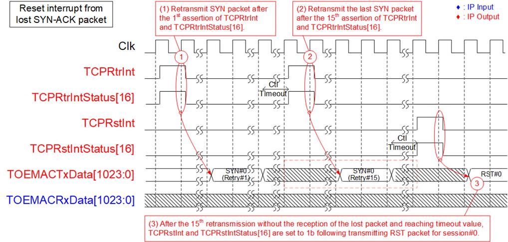
Figure 33 TCPRstIntStatus[16] Assertion
1) The first retransmission of the SYN packet for session#0 is initiated following the assertion of the TCPRtrInt and TCPRtrIntStatus[16] signals.
2) In the absence of receiving the SYN-ACK packet, the process outlined in step (1) repeats for a total of 15 iterations. The SYN#0 (Retry#15) packet is transmitted during the final round.
3) Upon reaching the timeout threshold, it triggers the assertion of TCPRstInt and TCPRstIntStatus[16] to initiate the transmission of the RST packet for session#0 to the target.
Reset Interrupt for Lost FIN-ACK packet (TCPRstIntStatus[18])
The reset interrupt can be triggered under specific conditions without any attempt at a retry process. Within the TOE200GADV IP, three bits of TCPRstIntStatus are allocated for each session to indicate three distinct types of this reset interrupt. For session#0, bit[18], bit[24], and bit[25] are designated for the reset interrupt, triggered in scenarios where no retry process is initiated. These conditions include the loss of FIN and ACK packets during active close operation, the reception of RST packet, and the reception of an unsupported packet. Further details regarding bit assignments for other sessions can be found in Table 9.
Table 9 Bit Assignment of TCPRstIntStatus for Session Interrupt without Retry Process
|
Interrupt status |
Session#0 |
Session#1 |
Session#2 |
Session#3 |
|
Lost FIN and ACK (active close) |
bit[18] |
bit[34] |
bit[50] |
bit[66] |
|
RST packet reception |
bit[24] |
bit[40] |
bit[56] |
bit[72] |
|
Unsupported packet reception |
bit[25] |
bit[41] |
bit[57] |
bit[73] |
This section presents an example that illustrates a situation involving the loss of FIN and ACK packets during the termination of a connection in active mode. The subsequent steps, outlining the transmission of the RST packet following the detection of lost FIN and ACK packets, are detailed below.
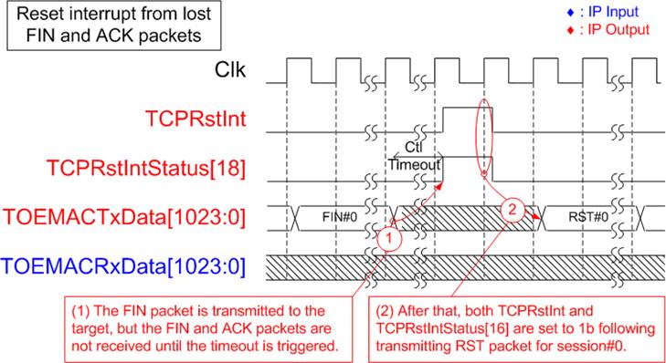
Figure 34 TCPRstIntStatus[18] Assertion
1) Following the user’s request of an active close command for session#0, a FIN packet is transmitted to the target. However, the target does not transmit FIN and ACK packets until the timeout value, as defined by TCPCtlTimeOutSet signal, is reached.
2) When the timeout duration is reached, both TCPRstInt and TCPRstIntStatus[18] are set to 1b, indicating the activation of the reset interrupt type. Subsequently, the RST packet is dispatched to the remote target to terminate the connection of session#0.
The User Interface of TOEMACIF
The TOEMACIF module serves as the interface connecting the TOE200GADV IP and the 600G Multirate Ethernet Subsystem (DCMAC). It is provided separately from the TOE200GADV IP, enabling users to integrate additional modules for Ethernet packet transmission through the Ethernet Subsystem. This integration is accomplished by connecting the additional modules to the user interface of TOEMACIF, which is notably simpler compared to the user interface of the DCMAC.
The TOEMACIF comprises
two submodules, allowing for concurrent packet transfer in both transmission
and reception directions. The user interface of TOEMACIF is compatible with the
1024-bit AXI4-ST bus, but it does not include a ‘Ready’ signal to pause data
transmission in the Rx user interface. This section provides comprehensive
information regarding the user interface of the TOEMACIF module, covering both
transmit and receive directions. For details of the 512-bit Segmented AXI4-ST
I/F, please refer to the AMD website.
TOEMACIF Tx Interface
Tx user interface of TOEMACIF does not include a control signal to indicate the start of a packet. Instead, TOEMACIF detects the first data of the packet when the first data is received after the end of the preceding packet or after a reset process. Given that the Ethernet Subsystem necessitates continuous data transmission for each packet transfer, TOEMACIF requires the Tx user interface to maintain TOEMACTxValid asserted until the last data of packet is completely transmitted. If the TxMAC buffer becomes full during packet transfer, TOEMACTxReady is set to 0b to temporarily pause packet transmission. Typically, every bit of the ‘Keep’ signal is asserted to 1b to indicate that every byte of transmit data is valid except for the last data cycle. TOEMACTxKeep can indicate the number of valid bytes of TOEMACTxData from 1-128 bytes at the last data strobe. Additional details regarding packet transmission through the Tx interface of TOEMACIF are provided below.
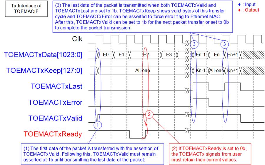
Figure 35 Tx Interface of TOEMACIF
1) To initiate packet transmission, the first data of packet is sent via TOEMACTxData, and TOEMACTxValid is asserted to 1b. If this data is not the last one, all 1024 bits of data must be valid, with TOEMACTxKeep set to all ones. Subsequently, TOEMACTxValid must remain asserted at 1b to ensure continuous packet transfer until the last data of the packet has been successfully transmitted.
2) While transmitting the packet, if the internal buffer of TOEMACIF (TxMAC buffer) reaches its capacity, TOEMACTxReady is set to 0b, temporarily pausing data transmission. During this period, input signals including TOEMACTxData, TOEMACTxKeep, TOEMACTxLast, TOEMACTxError, and TOEMACTxValid must maintain their values until TOEMACTxReady is re-asserted to 1b.
3) Upon transmitting the last data of the packet, both TOEMACTxLast and TOEMACTxValid are set to 1b. During the last transfer cycle, TOEMACTxKeep is set to indicate the number of valid bytes in TOEMACTxData. Additionally, user can set TOEMACTxError to 1b to indicate frame error status. Following this, the user can choose to proceed with the next packet transmission by setting TOEMACTxValid to 1b or pause packet transmission by setting TOEMACTxValid to 0b.
TOEMACIF Rx Interface
When data is available in the RxMAC buffer, TOEMACIF initiates packet transfer by setting TOEMACRxValid to 1b. Packet transmission may pause temporarily when no more data remains in the RxMAC buffer. During the last data transfer cycle, it is important for the user to verify TOEMACRxError to ensure that the packet does not contain any errors. If an error is asserted, the packet must be discarded. Additional information about packet reception through the Rx interface of TOEMACIF is provided below.
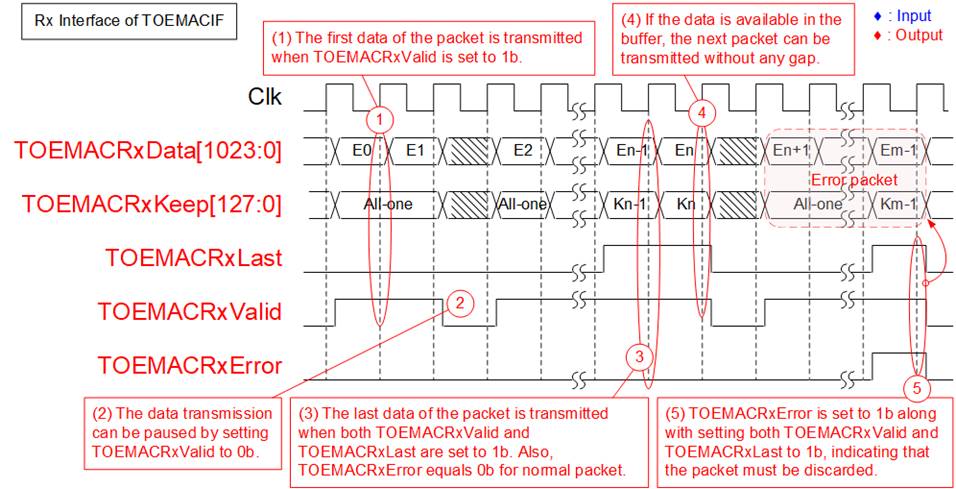
Figure 36 Rx Interface of TOEMACIF
1) Upon receiving an Ethernet packet from the Ethernet Subsystem, the packet is subsequently stored in the RxMAC buffer. Once data becomes accessible within the RxMAC buffer, the packet transmission through the Rx user interface is initiated. If this is the first data of the packet, TOEMACRxValid is set to 1b, and the data is transmitted via the TOEMACRxData signal. If this is not the last data, TOEMACRxKeep is always set to all ones, indicating that all 1024-bit data is valid.
2) If there is no data available in the RxMAC buffer, the transmission of data can be temporarily halted during the transfer of each packet by setting TOEMACRxValid to 0b.
3) The last data of the packet is transferred through TOEMACRxData when both TOEMACRxLast and TOEMACRxValid are set to 1b. During this cycle, TOEMACRxKeep may not be equal to all ones if the number of valid bytes of TOEMACRxData is less than 128 bytes. Additionally, it needs to check TOEMACRxError to ensure that it is not asserted to 1b from any errors.
4) If data remains in the RxMAC buffer, the next packet will be transferred in the next clock cycle by setting TOEMACRxValid to 1b, initiating the transfer of the first data of the packet. Otherwise, TOEMACRxValid is set to 0b.
5) In case the incoming packet contains any errors, TOEMACRxError will be set to 1b during the last data transfer cycle, indicated by TOEMACRxLast being set to 1b. In this situation, the user must discard this error packet.
The Assertion of MACRxInt when RxMAC buffer Overflow
TOEMACIF includes a 64KB RxMAC buffer designed to store received packets from the Ethernet Subsystem (DCMAC). When the ‘Clk’ frequency is set to the recommended value, TOEMACIF efficiently converts Ethernet packets, which are in a 512-bit Segmented AXI4-ST format from the DCMAC, into the 1024-bit AXI4-ST interface without experiencing packet loss in most scenarios. However, there are theoretical situations in which this buffer may reach its maximum capacity. For instance, continuous reception of 64-byte Ethernet packets without interruption, along with a ‘Clk’ frequency set lower than the ‘MACClk’ frequency (390.625 MHz), can lead to insufficient bandwidth for the 1024-bit AXI4-ST interface compared to the 512-bit Segmented AXI4-ST I/F. This situation may eventually result in the RxMAC buffer reaching its storage limit.
In comparison to the Rx Segmented AXI4-ST I/F of the DCMAC, the TOEMACIF module’s interface includes an additional signal called MACRxInt. This signal serves to indicate when the RxMAC buffer reaches full capacity, prompting TOEMACIF to discard incoming packet from the DCMAC and await the next packet transmission. Because the discarded packet is not written into the RxMAC buffer, the buffer occupancy does not increase further. As buffered data continues to be read on the TOE side, free space becomes available and normal packet reception can resume.
For more detailed information about the assertion of MACRxInt when a packet is discarded, please refer to the following section.
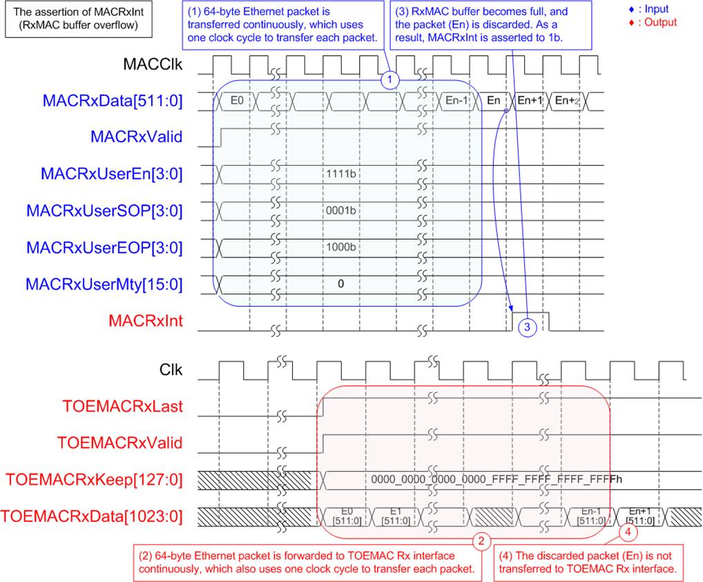
Figure 37 MACRxInt Assertion After the RxMAC Buffer Overflow
1) Consider a continuous stream of 64-byte Ethernet packets arriving, with each packet being completely transmitted in a single clock cycle.
2) For 64-byte packets, both interfaces require approximately one clock cycle per packet. Therefore, when Clk is lower than MACClk, the TOE-side packet-processing rate is lower and packets can accumulate in the RxMAC buffer, even though the TOE-side data bus is wider.
3) If this sustained data transfer continues for an extended period, the RxMAC buffer will eventually reach its capacity. At this point, incoming packet (En) will be discarded, triggering the assertion of MACRxInt to 1b.
4) The TOEMAC Rx interface, as depicted in Figure 37, handles the transfer of packets, with ‘En-1’ being followed by ‘En+1’, while the discarded packet (En) is omitted.
Connection Termination in Unusual Cases
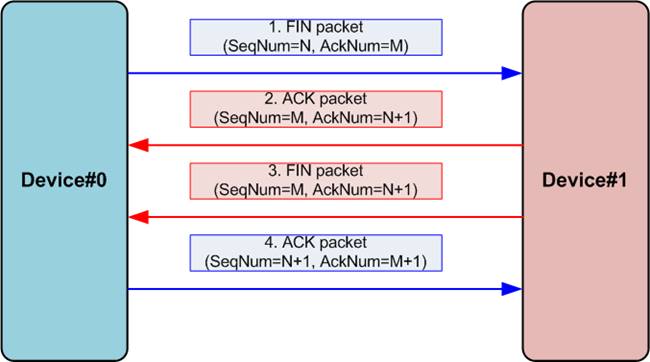
Figure 38 Connection Termination Sequence
The process of terminating a connection in the standard scenario is illustrated in Figure 38. The figure shows a four-packet exchange between two devices, where the ACK and FIN packets from Device#1 are transmitted separately. If the ACK and FIN are combined into a single packet, only three packets are exchanged.
In this sequence, the first device (Device#0) initiates connection termination by sending a FIN packet. If the second device (Device#1) agrees to terminate the connection, it responds with both ACK and FIN packets, which may be combined into a single packet or transmitted separately. Finally, Device#0 confirms the termination by sending an ACK packet, completing the connection termination sequence. This section describes the operation of the TOE200GADV IP in several unusual connection-termination cases.
Note: TOE200GADV-IP does not support TCP half-close after a local Active Close. After transmitting FIN, TCP payload data subsequently received from the target is discarded; only the expected ACK/FIN control packets are accepted until connection termination completes.
· When the TOE200GADV IP receives an active close command from the user, it sends a FIN packet to commence the connection termination process. Subsequently, the TOE200GADV IP awaits FIN and ACK packets that contain specific values for the sequence number (SeqNum) and acknowledgement number (AckNum). Assuming that a FIN packet emitted by the TOE200GADV IP assigns SeqNum=N and AckNum=M, the expected values of SeqNum and AckNum in the received FIN and ACK packets are M and N+1, respectively. If these expected packets are not received within the designated timeout period, without any retry attempts, the TOE200GADV IP transmits a RST packet to terminate the connection.
· Following the execution of an active close command operation, the TOE200GADV IP ceases to accept additional data from the target. Any received packet containing data is discarded, similar to the first case. The IP only accepts FIN and ACK packets that match the expected values of SeqNum and AckNum.
· If the target initiates the connection termination by sending a FIN packet while the TOE200GADV IP still has remaining data for transmitting, the TOE200GADV IP accepts the termination request and halts data transmission. It responds with FIN and ACK packets to the target, with the SeqNum value configured to match the most recently confirmed data acceptance value. Users can determine the amount of unsent data by monitoring the TOETxStat[19:0] signal. Additional details of this case can be found in Figure 16.
Verification Methods
The TOE200GADV IP Core functionality was verified by simulation and also proved on real board design by using VHK158 and VPK120 board.
Recommended Design Experience
Experienced design engineers with a knowledge of Vivado Tools should easily integrate this IP into their design.
Ordering Information
This product is available directly from Design Gateway Co., Ltd. For pricing and additional information about this product, please refer to the contact information on the front page of this datasheet.
Revision History
|
Revision |
Date (D-M-Y) |
Description |
|
2.00 |
26-Aug-26 |
Support data alignment configurable options Add MSSInitValSet and TCPAckDlyTimeSet to IO Signals |
|
1.00 |
13-Nov-24 |
Initial release |