TOE200GADV-IP Reference Design Manual
2.1 Versal Adaptive SoC 600G Channelized Multirate Ethernet Subsystem (DCMAC)
3.1 Test Firmware (toexgadvtest.c)
3.2 Function List in Test Firmware
3.2.1 Function for High-Speed Connection
3.2.2 Function for Low-Speed Connection
4.1 “tcpdatatest” Application (Half Duplex Test)
4.2 “tcp_client_txrx_single” Application (Full Duplex Test)
1 Overview
The TCP/IP (Transmission Control Protocol/Internet Protocol) suite is fundamental to network communications, facilitating data transfers across various networks with reliability. Typically, the host system utilizes a CPU to manage the TCP/IP stack via its operating system, which must also share resources among various tasks. Consequently, the performance of data transfer through a single TCP session is limited when relying on such CPU-based system.
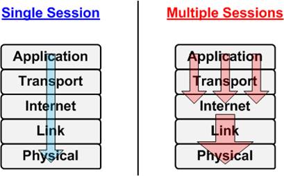
Figure 1 Multiple TCP Sessions Concept
To overcome this limitation, several researchers have proposed employing multiple TCP sessions. As shown in Figure 1, this concept creates a pipelined data flow in the upper layers, significantly increasing data volume and improving utilization of the lower layer bandwidth. However, this approach introduces another challenge: managing multiple TCP/IP sessions can consume significant CPU and OS resources.
To address these challenges, Design Gateway introduces the TOE200GADV-IP, a hardwired logic on an FPGA that implements the Transport and Internet layers of the TCP/IP Protocol. This IP Core fully offloads TCP/IP packet processing and incorporates a native multi-session architecture. It supports up to four simultaneous sessions on the same 200G Ethernet channel, significantly enhancing overall performance for data transfer between the FPGA and PC. Additionally, four TCP sessions can be utilized to transfer different data types simultaneously for the applications that require varied data types during system execution. In scenarios where data transfer occurs between two FPGAs via TOE200GADV-IP, using a single TCP session can achieve the peak performance of 200G Ethernet.
The TOE200GADV-IP is specifically designed for the rapid transmission of TCP payload data, making it well-suited for applications demanding ultra high-speed connectivity across all four TCP sessions. However, specific applications necessitate a designated port for the transfer of control information using alternative protocols like ICMP or DHCP, where high-speed transfer is not required. In response to this demand for lower-speed transfer, dedicated logic for CPU interface has been incorporated to optimize resource utilization and provide flexibility in handling varied processing requirements.
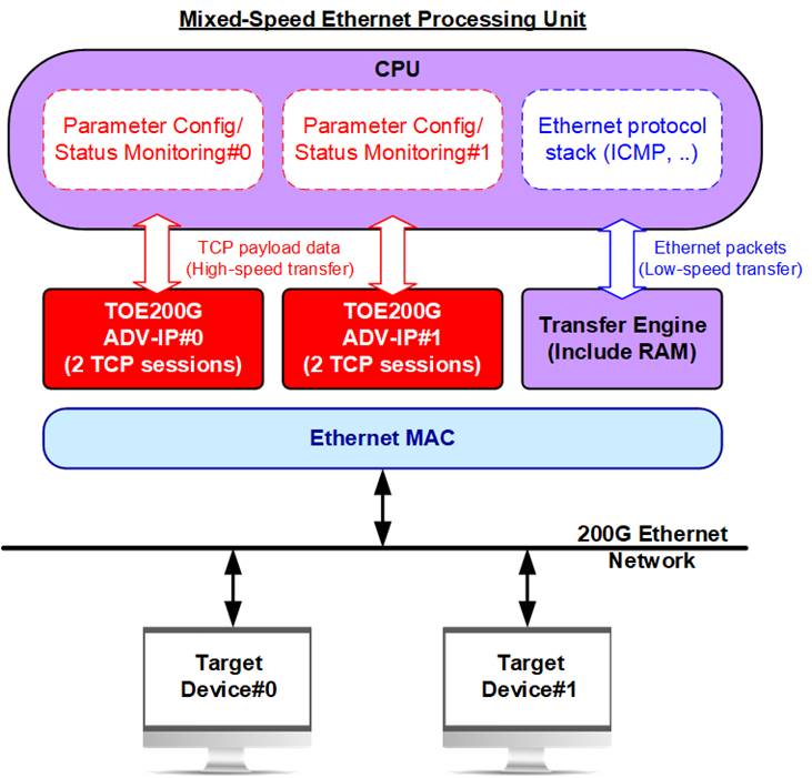
Figure 2 Mixed-speed and Versatile Ethernet Processing Unit
The system shown in Figure 2 illustrates this concept effectively. Since one instance of TOE200GADV-IP can communicate with only one target device at a time, the base system incorporates two TOE200GADV-IP instances to support simultaneous communication with two target devices. Each IP core is configured to support two TCP sessions, enabling four high-speed TCP sessions to operate concurrently. Meanwhile, the CPU handles the remaining ports and other lower-speed protocols.
This document outlines the reference design aligned with the system architecture shown in Figure 2. In this design, the CPU handles the Ping command via the ICMP protocol, while two TOE200GADV-IP cores manage four high-speed sessions. The reference design implements four TCP sessions. Users can independently select which sessions participate in each test. This feature supports performance testing and operational validation even with fewer than four sessions.
In addition, each session’s data transfer direction (send, receive, or full-duplex) can be individually configured to suit specific use cases. Users can also customize the multi-session reference design by adjusting the number of sessions as needed.
To improve demo usability, a UART interface is included in the CPU system, providing a user console for setting test parameters, controlling demo execution, and monitoring test status. The CPU firmware is implemented as bare-metal firmware without an operating system. Further details of the reference design are provided in the subsequent sections.
2 Hardware
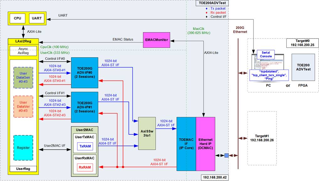
Figure 3 Demo Block Diagram
The reference design implements a system on FPGA that integrates two TOE200GADV-IPs, enabling simultaneous high-speed communication with two target devices over 200G Ethernet. Each target device can be either a PC for standard testing or another FPGA integrating the TOE200GADV-IP for high-performance evaluation.
Each TOE200GADV-IP must be configured to determine how the destination MAC address is obtained or assigned. Client and Server modes obtain the address through ARP, while Fixed-MAC mode uses the user-defined DstMacAddrIn value. Once the configuration is complete, data transfer testing can begin. To support high-speed TCP payload transfer on a PC, two applications are provided: ‘tcpdatatest’ for half-duplex transfer and ‘tcp_client_txrx_single’ for full-duplex transfer. For low-speed testing, the standard ‘Ping’ command is used.
The reference design supports two types of Ethernet communication: a low-speed connection managed by the CPU and a high-speed connection handled by the TOE200GADV-IP. In the low-speed connection, the CPU firmware implements the ICMP protocol for Ping testing. Ethernet packets in this connection are transferred through the User2MAC interface, with CPU-configured parameters to handle only ICMP packets. The User2MAC block includes TxRAM and RxRAM to store Ethernet packets being transmitted to or received from the Ethernet Hard IP (DCMAC). The UserReg module provides CPU access to these RAMs.
In the high-speed connection, two TOE200GADV-IPs are used to process TCP payload data for communication with two target devices. Each IP supports data transfer using one or two TCP sessions. The CPU configures the parameters of both TOE200GADV-IPs using the 32-bit UserReg register interface. Data interfaces of each TCP session are managed by the respective UserDataGen and UserDataVer modules. Although each TOE200GADV-IP supports up to four TCP sessions, only two sessions per IP are configured in this reference design to reduce overall FPGA resource usage, making it more suitable for smaller FPGA boards.
The system can simultaneously process Ethernet packets from both high-speed and low-speed connections. However, for basic functional testing, the CPU firmware’s main menu allows the user to select either high-speed or low-speed operation. The AxiSSw3to1 module functions as a packet source selector, forwarding data to the TOEMACIF module. Packet sources include User2MAC, TOE200GADV-IP#0, and TOE200GADV-IP#1. The receive output interface of TOEMACIF is connected directly to all three sources. Each TOE200GADV-IP and User2MAC include packet filtering logic to selectively allow or discard packets based on the header values.
To connect with 200G Ethernet, the Versal ACAP 600G Channelized Multirate Ethernet MAC (DCMAC), integrated into AMD Versal devices, is configured for 200G Ethernet operation with the PCS/PMA layers enabled. In this configuration, the DCMAC provides a 512-bit segmented AXI4-ST user interface. However, this interface does not directly match the 1024-bit AXI4-ST interface used by the TOE200GADV-IP and User2MAC modules. Consequently, adapter logic, TOEMACIF, is used to convert between these interfaces. This adapter is provided as part of the TOE200GADV-IP suite.
The reference design incorporates three distinct clock domains: CpuClk for the CPU system, MacClk for the Ethernet Hard IP (DCMAC), and UserClk for the user logic of the TOE200GADV-IP. To facilitate asynchronous signal transfer between CpuClk and UserClk, the AsyncAxiReg module is used. The reference design sets UserClk to approzimately 333 MHz. This is above the minimum operating frequency specified for TOE200GADV-IP and provides additional processing margin to reduce the possibility of RxPac-buffer overflow during continuous high-rate traffic based on the transfer of 640-byte payload packets. Further details about each module within the TOE200GADVTest are provided below.
2.1 Versal Adaptive SoC 600G Channelized Multirate Ethernet Subsystem (DCMAC)
The DCMAC integrates the MAC, PCS, and PMA functions required for 200Gb Ethernet operation. This IP Core provides a 512-bit Segmented AXI4-ST interface operating at 390.625 MHz, necessitating adapter logic (TOEMACIF) for proper interfacing with the TOE200GADV-IP. For more comprehensive information, please refer to “Versal Adaptive SoC 600G Channelized Multirate Ethernet Subsystem (DCMAC) LogiCORE IP Product Guide” on the AMD website.
https://docs.amd.com/r/en-US/pg369-dcmac/Introduction
In this reference design, the recommended configuration parameters for the DCMAC Hard IP are as follows:
System Configuration
· DCMAC Operating Mode : Coupled MAC+PCS
· AXIS Datapath Interface : 391MHz Upto 6 Prots
· MAC Port0 Enabled : Checked
· MAC Port0 Tx FCS Insert : Checked
· Default PCS Mode : 200GAUI-4
· FEC mode : RS(544) CL119
2.2 EMACMonitor
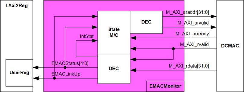
Figure 4 EMACMonitor Block diagram
To generate the Ethernet status signals, including the link-up status (EMACLinkup) and other Ethernet status information (EMACStatus), the EMACMonitor reads status information from internal DCMAC registers through the AXI4-Lite interface and decodes the retrieved values. The generated EMACLinkup and EMACStatus signals are mapped to EMAC_STS_INTREG, as defined in Table 1.
Since the DCMAC status information is accessed through the AXI4-Lite interface, EMACMonitor uses a state machine to control the AXI4-Lite read transactions. The state machine continuously monitors the PHY/PCS and MAC status of the DCMAC to determine the current Ethernet link condition. The operation is described as follows:
1) Read the PHY/PCS status register of the DCMAC and verify that FEC alignment and Rx PCS lock are established. When both status conditions are valid, proceed to the next step.
2) Read the MAC status register and verify that neither a local fault nor a remote fault is detected. If the PHY/PCS status is valid and no MAC fault is detected, assert EMACLinkup to 1b and proceed to the next step.
3) Continue monitoring the PHY/PCS and MAC status to verify that the Ethernet link remains valid. If a PHY/PCS error or MAC fault is detected, de-assert EMACLinkup to 0b. The state machine then returns to the corresponding monitoring state to wait until the Ethernet link is re-established.
2.3 TOEMACIF
The TOEMACIF serves as adapter logic to seamlessly connect the TOE200GADV-IP with the DCMAC. It facilitates the interface conversion between the 1024-bit AXI4-ST interface of the TOE200GADV-IP and the 512-bit Segmented AXI4-ST interface of the DCMAC.
Additionally, TOEMACIF is responsible for managing packet transfers across different clock domains between UserClk and MacClk. This adapter is provided as an additional IP core, delivered with the TOE200GADV-IP. For further details about TOEMACIF, please refer to the TOE200GADV-IP datasheet available on our website:
https://dgway.com/products/IP/TOE200G-IP/toe200gadv-ip-datasheet-amd/
2.4 AxiSSw3to1
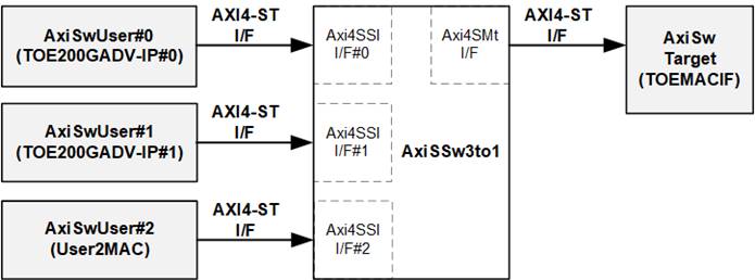
Figure 5 AxiSSw3to1 Interface
The AxiSSw3to1 module functions as a 3-to-1 switch for AXI4-ST interface, enabling the transfer of transmitted data from AxiSwUser (TOE200GADV-IP#0, TOE200GADV-IP#1, or User2MAC) to AxiSwTarget (the TOEMACIF). The module includes configurable parameters to define the data width and user-defined signal width. In this reference design, the data width for User2MAC and both TOE200GADV-IPs is configured to 1024 bits, while the user-defined signal width is set to 1 bit.
Conceptually, AxiSSw3to1 operates by routing data from three users (Ch#0, Ch#1, and Ch#2) to a single target via AXI4-ST interface. When multiple users request data transfer simultaneously, the module employs a priority mechanism, selecting the highest priority channel to transfer a complete packet. Once the packet is fully transmitted, the priority shifts to the next channel, allowing its data stream to be sent through the interface.
The control signal ‘rChSel’ is used to select the active user, representing the current user channel granted access. The priority mechanism is based on a round-robin sequence (0 -> 1 -> 2 -> 0 …). The determination of the next active channel depends on two factors: the current user channel (rChSel) and the current operating status of the module.
· If the module is actively forwarding a packet, the highest priority user is assigned to the next channel in the round-robin sequence. For example, if the current active user is 0, the highest priority user becomes 1.
· If the module is idle, the highest priority remains with the current user. For example, if the current user is 0, it retains the highest priority.
Further operational details and timing behavior are illustrated in Figure 6.
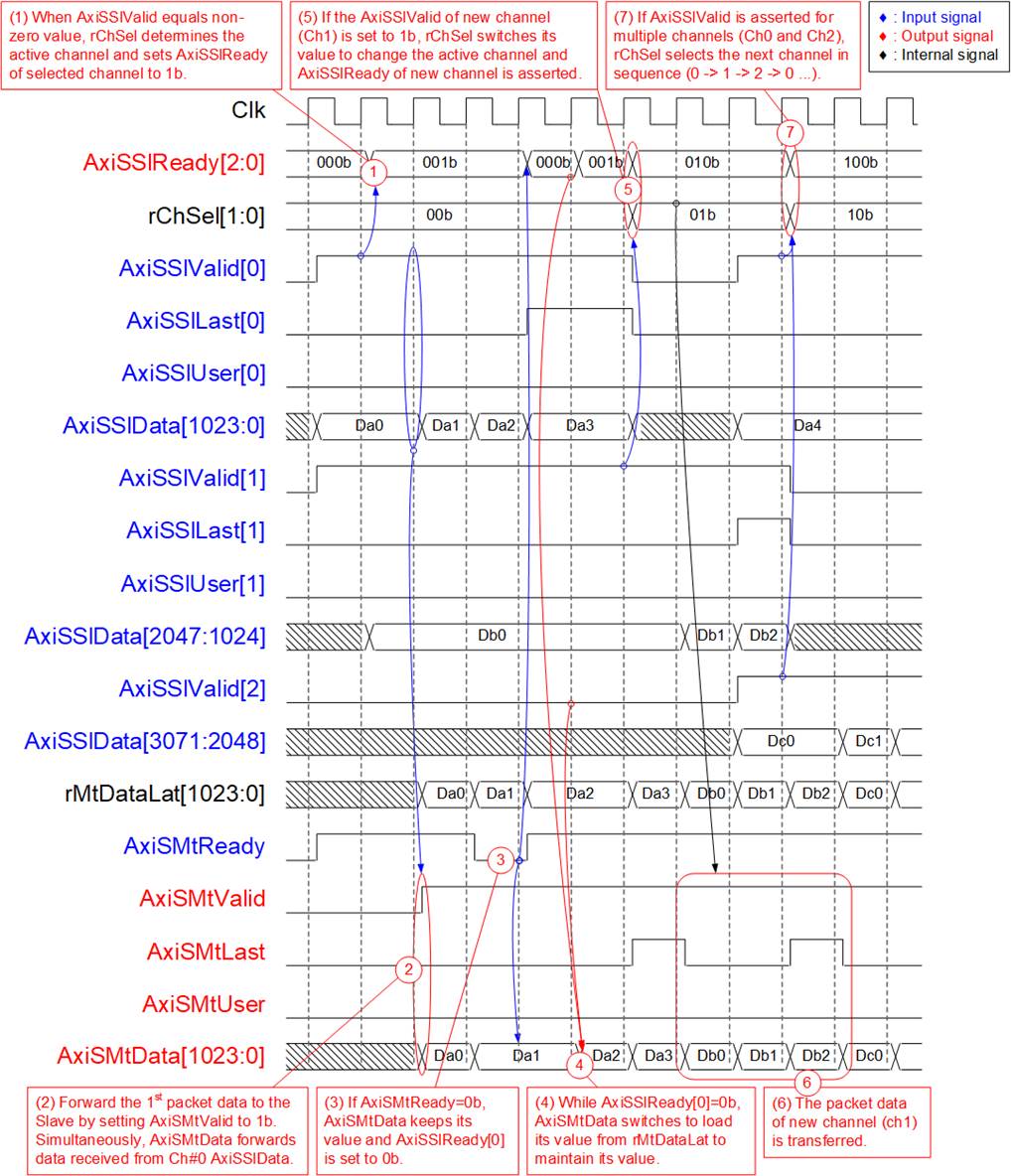
Figure 6 AxiSSw3to1 Timing Diagram
1) The module is currently idle, so the highest priority user remains unchanged (rChSel=00b, corresponding to User#0). When both User#0 and User#1 assert AxiSSlValid simultaneously, the request from User#0 is granted by asserting AxiSSlReady[0]=1b, enabling acceptance of the first data word from User#0.
2) The input signals from the selected user (User#0), including AxiSSlLast[0] (end-of-packet), AxiSSlUser[0] (user-defined signal), and the 1024-bit AxiSSlData[1023:0], are forwarded to the target through the Master interface as AxiSMtLast, AxiSMtUser, and AxiSMtData, respectively. The AxiSMtValid signal is asserted to 1b, indicating that a new packet transmission has begun.
3) If the target is not ready to receive data, indicated by AxiSMtReady=0b, all output signals on the Master interface retain their current values. At the same time, AxiSSlReady[0] is de-asserted to 0b, ensuring that the current input signals from the user remains unchanged.
4) Once the target reasserts AxiSMtReady to 1b, the output signals to the target are updated with the next values stored in the internal latch register (rMtDataLat). This register holds the most recent data from the active user when AxiSSlReady was previously asserted to 1b, ensuring that no data is lost if transmission was temporarily paused.
5) After the final data of the packet from the User#0 is successfully transmitted, the module scans for other active channels. If another channel has AxiSSlValid asserted, rChSel is updated to reflect the next user. In this example, rChSel switches to 01b, selecting User#1, and data transmission from User#1 begins.
6) The input signals from User#1, including AxiSSlLast[1], AxiSSlUser[1], and AxiSSlData[2047:1024], are passed through as the output signals of the Master interface (AxiSMtLast, AxiSMtUser, and AxiSMtData) until the entire packet is transferred.
7) During transmission of the last packet data from User#1, both User#0 and User#2 assert AxiSSlValid simultaneously. Based on the round-robin priority logic, the next user in sequence after User#1 is User#2. Therefore, ‘rChSel’ is updated to 10b, and AxiSSlReady[2] is asserted to 1b, beginning packet transfer from User#2 to the target.
2.5 TOE200GADV-IP
The TOE200GADV-IP implements a TCP/IP offloading engine capable of handling four TCP sessions with the same target device.
The user data interface uses a 1024-bit AXI4-ST interface. The control interface is responsible for configuring network parameters, sending command requests, and monitoring operational status. Similarly, the Ethernet MAC interface also operates through a 1024-bit AXI4-ST interface.
For more detailed information about the IP core, please visit our website:
https://dgway.com/products/IP/TOE200G-IP/toe200gadv-ip-datasheet-amd/
2.6 User2MAC
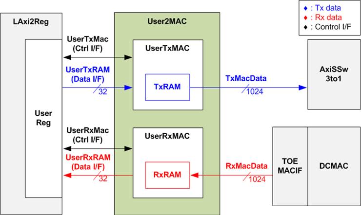
Figure 7 User2MAC Block Diagram
User2MAC is designed for transferring Ethernet packets in low-speed connection. The reference design incorporates the Ping command, using the ICMP protocol, to measure round-trip time. An ICMP Echo reply packet is generated upon receiving an ICMP Echo request packet.
The CPU firmware creates and decodes Ethernet packets and accesses User2MAC through LAxi2Reg. The LAxi2Reg side uses a 32-bit register interface, while the User2MAC MAC-side data path is 1024 bits.
User2MAC operates in both transmission and reception modes, consisting of two modules: UserTxMAC and UserRxMAC. UserTxMAC includes TxRAM, where the CPU prepares and stores Ethernet packets to be transmitted. Meanwhile, UserRxMAC features RxRAM to store Ethernet packets received from the Ethernet MAC. Before storing a packet in RxRAM, the filtering logic compares selected bytes within the first 38 bytes of the received packet against the configured header values. Only valid packets are stored, while invalid ones are discarded. The CPU then reads from RxRAM to decode the stored packets.
Further details about the functionalities and operations of UserTxMAC and UserRxMAC are provided in the subsequent sections.
2.6.1 UserTxMAC
UserTxMAC includes 32 x 1024-bit simple dual port RAM for storing packets to be transmitted. The CPU writes these packets to the RAM via the UserTxRam Write I/F. The CPU sets the packet size (UserTxMacLen) and asserts a request (UserTxMacReq) to initiate the logic that forwards the packet, read from TxRAM, to the Ethernet MAC (EMAC). The UserTxMAC transmit interface toward AxiSSw3to1/TOEMACIF is a 1024-bit AXI4-ST I/F, which may de-assert its ready (TxReady) to temporarily pause data transmission. Upon completion of the packet transmission to EMAC, the busy signal (UserTxMacBusy) is de-asserted to 0b. Additional details about the internal logic design of UserTxMAC are illustrated in Figure 8.
Note: The UserTxRam Write I/F with the CPU utilizes a 32-bit data width, while the TxRAM data width is 1024 bits. Therefore, a decoder is implemented to create a write byte enable signal, allowing the CPU to write specific bytes of the 1024-bit data bus of TxRAM.
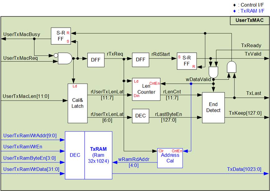
Figure 8 UserTxMAC Logic Diagram
The steps involved in transmitting a packet from UserTxMAC are outlined below.
1) The CPU verifies that UserTxMacBusy is 0b to ensure that UserTxMAC is in an idle state.
2) The CPU prepares the packet and writes it to TxRAM, starting at address 0 (UserTxRamWrAddr=0). TxRAM has a capacity of 4096 bytes. However, UserTxMacLen supports a valid packet length of 1–4095 bytes; therefore, the maximum transmitted packet size is 4095 bytes.
Note: TxRAM incorporates a byte-enable feature, allowing the CPU to write data at the byte level.
3) The CPU sets UserTxMacLen to specify the transmit packet size in bytes, and then asserts UserTxMacReq to 1b to initiate data transmission.
4) The request signal is processed by several logic blocks and a DFF chain. UserTxMacBusy is asserted to 1b, indicating that the transmission operation is in progress. The total transfer size (UserTxMacLen) is loaded into internal logic and divided into two parts.
· UserTxMacLen[11:7] determines the number of 1024-bit data, rounding up if the packet is not 1024-bit aligned.
· UserTxMacLen[6:0] is latched to generate the number of valid bytes for the final packet data (rLastByteEn and TxKeep) using a decoder.
5) When the start flag (rRdStart) is asserted, the first data is read from TxRAM, and the data valid (TxValid) is asserted to 1b. The read address (wRamRdAddr) is incremented to fetch the next data after each data transfer (TxValid=1b and TxReady=1b). Simultaneously, the Length counter (rLenCnt) is decremented to track the remaining data to be transmitted.
6) When rLenCnt=1 (indicating that the next data is the final data), the end-of-packet flag (TxLast) is asserted to 1b. Also, the byte enable (TxKeep) loads the value from rLastByteEn. For intermediate data (not the final data), TxKeep is set to all ones to represent full 1024-bit data transfer.
7) After the final data is transmitted, UserTxMacBusy is de-asserted to 0b, indicating the completion of the current transmission.
2.6.2 UserRxMAC
UserRxMAC performs three distinct operations to validate incoming packets and store valid packets in RxRAM, which is implemented as a 32 x 1024-bit simple dual port RAM. Accordingly, the logic within UserRxMAC is divided into three groups, as illustrated in Figure 9.
Note: The UserRxRam Read I/F for the CPU uses a 32-bit data width, while RxRAM internally operates with a 1024-bit data width. Therefore, a 32-to-1 multiplexer (Mux) is integrated to select 32-bit data from the 1024-bit data.
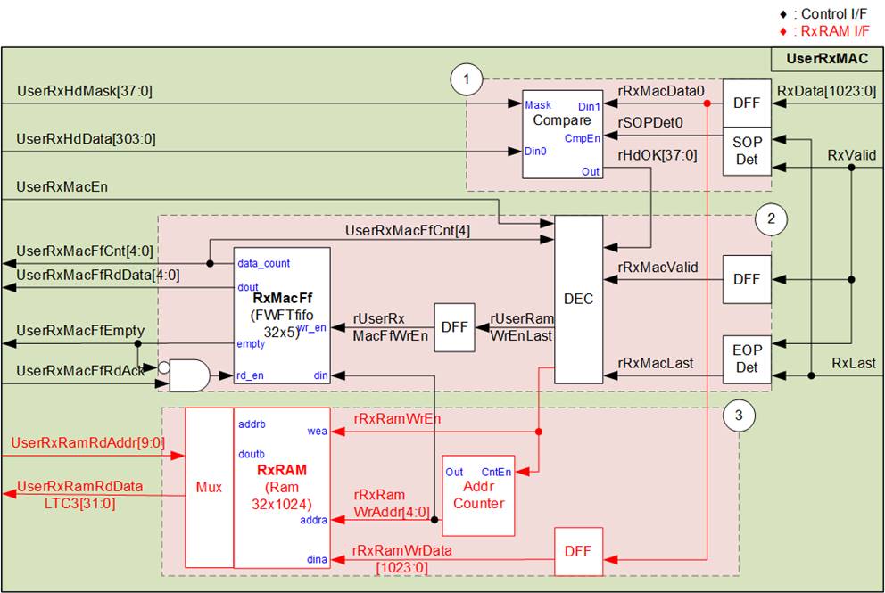
Figure 9 UserRxMAC Logic Diagram
Block no.1 contains the logic responsible for verifying the 38-byte packet header (byte#0 – #37) of each received packet. The user can configure the expected header values and associated mask bits for comparison. Only packets whose selected header bytes match the configured expected values are accepted for further processing.
Block no.2 checks both the user enable flag and the available space in RxMacFf. If the module is disabled by the user or if the FIFO lacks sufficient space, the packet is rejected. The RxMacFf stores the end address in RxRAM after a packet is stored, allowing the CPU to determine the size of the received packet based on this stored address.
Block no.3 handles writing the validated packet into RxRAM. The detailed sequence of UserRxMAC operations during packet reception is elaborated in the following sections.
Header Verification (Block no.1)
Two user-configured parameters, 38-byte header data (UserRxHdData) and a 38-bit data mask (UserRxHdMask), must remain stable when the user enables this module by asserting UserRxMacEn to 1b.
Upon receiving the first data of a new packet, SOPDet asserts rSOPDet0, triggering the Compare module. The received bytes #0-#37 are compared against UserRxHdData, with each byte comparison controlled by the corresponding bit in UserRxHdMask.
If a bit in the mask is de-asserted to 0b, that corresponding byte in the received packet is bypassed. Therefore, header verification is completely disabled if UserRxHdMask is set to all zeros. When a specific byte comparison passes, the corresponding bit in rHdOK is asserted to 1b. The packet is stored in RxRAM only when all 38 bits of rHdOK are set to 1.
Enable and Free Space Check (Block no.2)
Two signals are monitored: the user enable flag (UserRxMacEn) and the RxMacFf data counter (UserRxMacFfCnt). The logic checks that the CPU is ready to process received packets (UserRxMacEn=1b), and sufficient free space is available in RxMacFf (bit[4] of UserRxMacFfCnt must be 0b). If both conditions are satisfied and the packet header is valid, the write enable signal for RxRAM (rRxRamWrEn) is asserted, allowing the received data to be stored in RxRAM. When the end-of-packet is detected (EOPDet), a pulse of rUserRamWrEnLast is asserted. Subsequently, rUserRxMacFfWrEn is asserted to 1b to write the packet’s ending address into RxMacFf.
Note: Using bit[4] of UserRxMacFfCnt for space checking allows RxMacFf to store up to 16 packet-end addresses, while RxRAM has a total capacity of 4 KB. To guarantee buffering of 16 packets, each packet must be no larger than 256 bytes.
Valid packets are stored into RxRAM by asserting the write enable to RxRAM (rRxRamWrEn) when the data is received (RxValid=1b). The write address counter increments after each 1024-bit data is stored. The last address, upon receiving the end-of-packet, is stored in RxMacFf.
Once a received packet has been validated and successfully stored in RxRAM by the UserRxMAC hardware, the next phase involves the CPU handling process. While the hardware ensures packet verification and buffering of valid packets, the CPU is responsible for retrieving the stored data from RxRAM and performing further processing or interpretation as required by the application. The following steps describe how the CPU interacts with the RxRAM and RxMacFf to manage received packet data efficiently.
CPU Handling of Received Packets
1) The CPU monitors until the FIFO is not empty (UserRxMacFfEmpty=0b).
2) Once ready, the CPU reads the last packet address from UserRxMacFfRdData.
Note: RxMacFf operates as a FWFT FIFO, so the data is valid immediately for reading.
3) After reading, the CPU asserts UserRxMacFfRdAck to 1b to acknowledge and flush the read data from RxMacFf.
4) The CPU reads and processes the received packet from RxRAM, starting from the last known read position up to the last address retrieved from RxMacFf. Once packet processing is completed, the CPU returns to step (1) to await and process the next packet.
Note: UserRxRamRdAddr points to 32-bit data, whereas rRxRamWrAddr references 1024-bit data. Therefore, the CPU firmware must translate the 1024-bit based address from RxMacFf into a 32-bit based address before starting data reading from RxRAM.
2.7 CPU and Peripherals
The CPU system uses a 32-bit AXI4-Lite bus as the interface to access peripherals, such as the Timer and UART. The system also integrates an additional peripheral to access the test logic by assigning a unique base address and address range. To support CPU read and write operations, the associated hardware must comply with the AXI4-Lite bus standard. The LAxi2Reg module, illustrated in Figure 10, is specifically designed to connect the CPU system via the AXI4-Lite interface, in compliance with the standard.
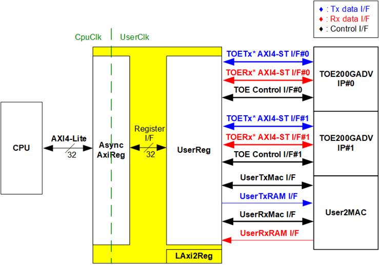
Figure 10 LAxi2Reg Block Diagram
The LAxi2Reg module consists of AsyncAxiReg and UserReg. The AsyncAxiReg converts AXI4-Lite signals into a simple Register interface with a 32-bit data bus size, matching the AXI4-Lite data width. It also provides asynchronous logic to handle clock domain crossing between the CpuClk and UserClk domains.
All user interfaces for the control/status signals and data signals of TOE200GADV-IP and User2MAC modules are mapped to UserReg. Control/status interfaces (represented in black) are translated and stored within the Register files inside UserReg. The data interface of TOE200GADV-IP employs an AXI4-ST interface, while the data interface for User2MAC uses a simple dual-port RAM interface.
Further details regarding AsyncAxiReg and UserReg are provided in the sections below.
2.7.1 AsyncAxiReg
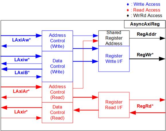
Figure 11 AsyncAxiReg Interface
The signals on AXI4-Lite bus interface are divided into five groups: LAxiAw* (Write address channel), LAxiw* (Write data channel), LAxiB* (Write response channel), LAxiAr* (Read address channel), and LAxir* (Read data channel). For more information on designing custom logic for the AXI4-Lite bus, refer to the following documentation.
In accordance with the AXI4-Lite standard, the write and read channels operate independently, with separate control and data interfaces for each channel. Therefore, the logic inside AsyncAxiReg that interfaces with the AXI4-Lite bus is divided into four functional groups: Write control logic, Write data logic, Read control logic, and Read data logic, as depicted on the left side of Figure 11. The Write control I/F and Write data I/F of the AXI4-Lite bus are latched and then transferred to the Write register interface via clock domain crossing registers. Similarly, the Read control I/F of the AXI4-Lite bus is latched and transferred to the Read register interface. The data returned from the Register Read I/F is transferred back to the AXI4-Lite bus by using clock domain crossing registers. In the Register interface, RegAddr is shared between write and read access, so the address is loaded from LAxiAw for write access or from LAxiAr for read access.
The simple register interface is designed to be compatible with a single-port RAM interface for write transaction. For read transaction, the Register interface is slightly modified from the RAM interface by adding RdReq and RdValid signals to control read latency. Since the address of the Register interface is shared for both write and read transactions, the user cannot perform simultaneous write and read operations. The timing diagram for the Register interface is shown in Figure 12.
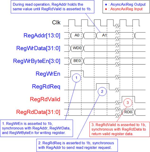
Figure 12 Register Interface Timing Diagram
1) Timing diagram to write register is similar to that of a single-port RAM. The RegWrEn signal is set to 1b, along with a valid value for RegAddr (the Register address in 32-bit units), RegWrData (write data for the register), and RegWrByteEn (write byte enable). The byte enable is four bits wide, where each bit indicates the validity of a specific byte within RegWrData. For example, if RegWrByteEn[0], [1], [2], and [3] are set to 1b, then RegWrData[7:0], [15:8], [23:16], and [31:24] are valid, respectively.
2) To read from a register, AsyncAxiReg sets the RegRdReq signal to 1b, along with a valid value for RegAddr. After the read request is processed, the 32-bit data is returned. The slave detects the RegRdReq being asserted to start the read transaction. During the read operation, the address value (RegAddr) remains unchanged until RegRdValid is set to 1b. Once valid, the address is used to select the returned data through multiple layers of multiplexers.
3) The slave returns the read data on RegRdData bus by setting the RegRdValid signal to 1b. After that, AsyncAxiReg forwards the read value to the LAxir* interface.
2.7.2 UserReg
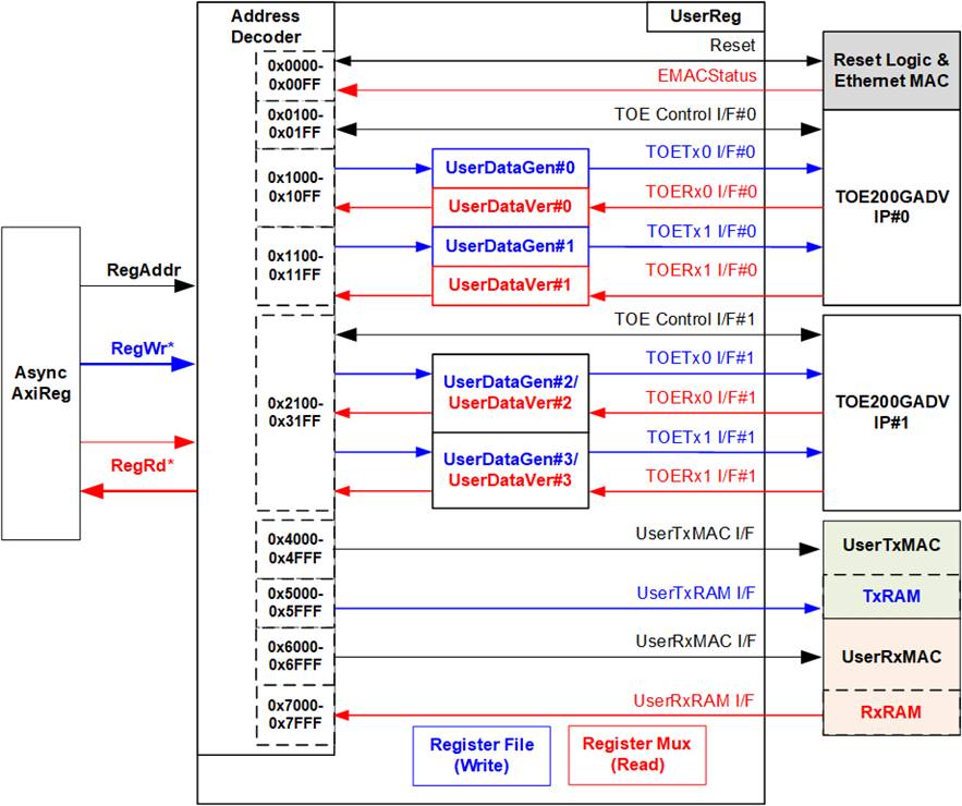
Figure 13 UserReg Block Diagram
As shown in Figure 13, an address decoder translates the user-assigned address to select the appropriate Register File during write operations. For read operations, the address value is input to multiple multiplexers to select the correct status signals returning to the user.
The address range of UserReg is partitioned as follows:
· 0x0000 – 0x00FF: Allocated for reset signals for each module and status signals of the Ethernet MAC.
· 0x0100 – 0x01FF: Allocated for control and status signals, including session statistics, for both Session#0 and Session#1 of TOE200GADV-IP#0.
· 0x1000 – 0x10FF: Allocated for control and status signals of UserDataGen#0 (data generation for TOE200GADV-IP) and UserDataVer#0 (data verification from TOE200GADV-IP), connected to TCP Session#0 of TOE200GADV-IP#0.
· 0x1100 – 0x11FF: Allocated for signals of UserDataGen#1 and UserDataVer#1, connected to TCP Session#1 of TOE200GADV-IP#0.
· 0x2100 – 0x21FF: Allocated for control and status signals, including session statistics, for both Session#0 and Session#1 of TOE200GADV-IP#1.
· 0x3000 – 0x30FF: Allocated for signals of UserDataGen#2 and UserDataVer#2, connected to TCP Session#0 of TOE200GADV-IP#1.
· 0x3100 – 0x31FF: Allocated for signals of UserDataGen#3 and UserDataVer#3, connected to TCP Session#1 of TOE200GADV-IP#1.
· 0x4000 – 0x4FFF: Allocated for control and status signals specific to UserTxMAC.
· 0x5000 – 0x5FFF: Allocated for the write interface of the TxRAM inside UserTxMAC.
· 0x6000 – 0x6FFF: Allocated for control and status signals specific to UserRxMAC.
· 0x7000 – 0x7FFF: Allocated for the read interface of the Rx RAM inside UserRxMAC
Using multiple multiplexers to select the appropriate status signals from various hardware submodules during read access introduces additional latency. To manage this, the RegRdValid signal is generated based on RegRdReq, with multiple D Flip-flops inserted to align timing and ensure the validity of the read data.
Further details regarding the address mapping within the UserReg module are summarized in Table 1.
Table 1 Register Map
|
Address |
Register Name |
Description |
|
Rd/Wr |
(Label in “toexgadvtest.c”) |
|
|
(BA+0x0000) – (BA+0x00FF): Reset and Ethernet MAC status signals |
||
|
BA+0x0000 |
Hardware Reset |
[0]: Set to 1b to reset TOE200GADV-IP#0, UserDataGen#0-#1, and UserDataVer#0-#1 modules. [1]: Set to 1b to reset TOE200GADV-IP#1, UserDataGen#2-#3, and UserDataVer#2-#3 modules. [8]: Set to 1b to reset Ethernet MAC. |
|
Wr/Rd |
(HW_RST_INTREG) |
|
|
BA+0x0040 |
Ethernet Statistics Reset |
[0]: Set to 1b to clear all statistic counters related to received Ethernet packets, including STATC_EMAC_INTREG, STATC_OVER_INTREG, and STATC_RXINTL/H_INTREG. This signal is asserted to 1b as a pulse and is automatically cleared to 0b. |
|
Wr/Rd |
(ETHSTAT_RST_INTREG) |
|
|
BA+0x0084 |
Ethernet MAC Status |
[0]: Ethernet MAC link status (0b-Link down, 1b-Link up) [4]: Tx Lock status of Ethernet MAC (0b-Not locked, 1-Locked) [5]: Rx CDR Lock status (0b-Not locked, 1-Locked) [6]: Rx alignment status (0b-Not aligned, 1b-Aligned) [7]: Rx PCS ready status (0b-Not ready, 1b-Ready) [8]: Remote Fault Code detection (0b-Not detected, 1b-Detected) |
|
Rd |
(EMAC_STS_INTREG) |
|
|
BA+0x0088 |
CRC Error Count |
[31:0]: Count the number of received Ethernet packets in which the EMAC detects a CRC error. |
|
Rd |
(STATC_EMAC_INTREG) |
|
|
BA+0x008C |
EMAC Buffer Overflow Count |
[31:0]: Count the number of received Ethernet packets discarded by TOEMACIF due to RxMACIF buffer overflow. |
|
Rd |
(STATC_OVER_INTREG) |
|
|
Address |
Register Name |
Description |
|
Rd/Wr |
(Label in “toexgadvtest.c”) |
|
|
(BA+0x0100) – (BA+0x01FF): Control and Status of TOE200GADV-IP#0 Further information of TOE200GADV-IP I/O signals is described in its datasheet. |
||
|
(BA+0x0100) – (BA+0x015F): Common Parameters and Status Signals of TOE200GADV-IP#0 |
||
|
BA+0x0100 |
TOE IP Version |
[31:0]: Mapped to IPVersion[31:0] of TOE200GADV-IP |
|
Rd |
(TOE_VER_INTREG) |
|
|
BA+0x0104 |
TOE Initialization Finish Flag |
[0]: Mapped to InitFinish of TOE200GADV-IP |
|
Rd |
(TOE_INF_INTREG) |
|
|
BA+0x0110 |
Source MAC Address-Low |
[31:0]: Mapped to SrcMacAddr[31:0] of TOE200GADV-IP |
|
Wr/Rd |
(TOE_SML_INTREG) |
|
|
BA+0x0114 |
Source MAC Address-High |
[15:0]: Mapped to SrcMacAddr[47:32] of TOE200GADV-IP |
|
Wr/Rd |
(TOE_SMH_INTREG) |
|
|
BA+0x0118 |
Dest MAC Address In-Low |
[31:0]: Mapped to DstMacAddr[31:0] of TOE200GADV-IP |
|
Wr/Rd |
(TOE_DMIL_INTREG) |
|
|
BA+0x011C |
Dest MAC Address In-High |
[15:0]: Mapped to DstMacAddr[47:32] of TOE200GADV-IP |
|
Wr/Rd |
(TOE_DMIH_INTREG) |
|
|
BA+0x0120 |
Source IP Address |
[31:0]: Mapped to SrcIPAddr[31:0] of TOE200GADV-IP |
|
Wr/Rd |
(TOE_SIP_INTREG) |
|
|
BA+0x0124 |
Dest IP Address |
[31:0]: Mapped to DstIPAddr[31:0] of TOE200GADV-IP |
|
Wr/Rd |
(TOE_DIP_INTREG) |
|
|
BA+0x0128 |
Dest MAC Mode |
[1:0]: Mapped to DstMacMode[1:0] of TOE200GADV-IP |
|
Wr/Rd |
(TOE_DMM_INTREG) |
|
|
BA+0x012C |
Window Threshold |
[9:0]: Mapped to WindowThres[9:0] of TOE200GADV-IP |
|
Wr/Rd |
(TOE_WIN_INTREG) |
|
|
BA+0x0130 |
TCP Control Timeout |
[31:0]: Mapped to TCPCtlTimeOutSet[31:0] of TOE200GADV-IP |
|
Wr/Rd |
(TOE_TCT_INTREG) |
|
|
BA+0x0134 |
TCP Receive Timeout |
[23:0]: Mapped to TCPRxTimeOutSet[23:0] of TOE200GADV-IP |
|
Wr/Rd |
(TOE_TRT_INTREG) |
|
|
BA+0x0138 |
TCP Initial MSS |
[13:0]: Mapped to MSSInitValSet[13:0] of TOE200GADV-IP |
|
Wr/Rd |
(TOE_MSS_INTREG) |
|
|
BA+0x013C |
TCP ACK Delay Timeout |
[9:0]: Mapped to TCPAckDlyTimeSet[9:0] of TOE200GADV-IP |
|
Wr/Rd |
(TOE_ACT_INTREG) |
|
|
BA+0x0140 |
Dest MAC Address Out-Low |
[31:0]: Mapped to DstMacAddrOut [31:0] of TOE200GADV-IP |
|
Rd |
(TOE_DMOL_INTREG) |
|
|
BA+0x0144 |
Dest MAC Address Out-High |
[15:0]: Mapped to DstMacAddrOut [47:32] of TOE200GADV-IP |
|
Rd |
(TOE_DMOH_INTREG) |
|
Address |
Register Name |
Description |
|
Wr/Rd |
(Label in the “toexgadvtest.c”) |
|
|
(BA+0x0160) – (BA+0x017F): Session Control and Status Signals of TOE200GADV-IP#0 |
||
|
BA+0x0160 |
Source Port Number |
[15:0]: Mapped to TCPSrcPort[15:0] of TOE200GADV-IP |
|
Wr/Rd |
(TOE_SPN_INTREG) |
|
|
BA+0x0164 |
Dest Port Number |
[15:0]: Mapped to TCPDstPort[15:0] of TOE200GADV-IP |
|
Wr/Rd |
(TOE_DPN_INTREG) |
|
|
BA+0x0168 |
TCP Last Mode |
[1:0]: Mapped to TCPLastMode[1:0] of TOE200GADV-IP |
|
Wr/Rd |
(TOE_LMD_INTREG) |
|
|
BA+0x016C |
TCP Command |
Wr [3:0]: Set value to TCPConnCmd[3:0] of TOE200GADV-IP When this register is written, the connection request (TCPConnReq) is asserted to initiate the TOE200GADV-IP operation. Rd [3:0]: The latest value of TCPConnCmd[3:0] set to TOE200GADV-IP [8]: Mapped to TCPConnReady of TOE200GADV-IP |
|
Wr/Rd |
(TOE_CMD_INTREG) |
|
|
BA+0x0170 |
TCP Connection ON |
[3:0]: Mapped to TCPConnOn[3:0] of TOE200GADV-IP |
|
Rd |
(TOE_CON_INTREG) |
|
|
BA+0x0174 |
TOE Interrupt |
Wr - Set the specified bit to 1b to clear the corresponding interrupt, read from this register. For instance, if bit[0] of TOE_INT_INTREG is set to 1b to indicate retry interrupt from common functions, users can set bit[0] of TOE_INT_INTREG to 1b to clear the interrupt, and the read value of this bit will become zero value. Rd – The interrupt status is activated by various conditions. [0]: Set to 1b when TCPRtrInt is triggered by common functions (TCPRtrIntStatus[15:0] is non-zero). [8]: Set to 1b when TCPConnCpl is triggered by Session#0 commands (TCPConnCplStatus[3:2] is 00b). [9]: Set to 1b when TCPConnCpl is triggered by Session#1 commands (TCPConnCplStatus[3:2] is 01b). [16]: Set to 1b when TCPRtrInt is triggered by Session#0 functions (TCPRtrIntStatus[31:16] is non-zero). [17]: Set to 1b when TCPRtrInt is triggered by Session#1 functions (TCPRtrIntStatus[47:32] is non-zero). [24]: Set to 1b when TCPRstInt is triggered by Session#0 functions (TCPRstIntStatus[31:16] is non-zero). [25]: Set to 1b when TCPRstInt is triggered by Session#1 functions (TCPRstIntStatus[47:32] is non-zero). |
|
Wr/Rd |
(TOE_INT_INTREG) |
|
|
BA+0x0178 |
RxPacBuf Overflow Count Low |
[31:0]: Lower 32 bits of a 48-bit counter indicating the number of received Ethernet packets discarded by TOE200GADV-IP due to RxPacBuf overflow. |
|
Rd |
(STATC_RXINTL_INTREG) |
|
|
BA+0x017C |
RxPacBuf Overflow Count High |
[15:0]: Upper 16 bits of a 48-bit counter indicating the number of received Ethernet packets discarded by TOE200GADV-IP due to RxPacBuf overflow. |
|
Rd |
(STATC_RXINTH_INTREG) |
|
|
Address |
Register Name |
Description |
|
Rd/Wr |
(Label in “toexgadvtest.c”) |
|
|
(BA+0x0180) – (BA+0x01FF): Session#0 - #1 Status Signals of TOE200GADV-IP#0 |
||
|
BA+0x0180 |
TCP Conn Status#0 Low |
[31:0]: Mapped to TCPConnStatus[31:0] of TOE200GADV-IP (session#0) |
|
Rd |
(TOE_TCS0L_INTREG) |
|
|
TCP Conn Status#0 High |
[31:0]: Mapped to TCPConnStatus[63:32] of TOE200GADV-IP (session#0) |
|
|
Rd |
(TOE_TCS0H_INTREG) |
|
|
BA+0x0188 |
TOE Transmit Status#0 |
[31:0]: Mapped to TOETxStat0[31:0] of TOE200GADV-IP (session#0) |
|
Rd |
(TOE_TTS0_INTREG) |
|
|
BA+0x018C |
TOE Receive Status#0 |
[31:0]: Mapped to TOERxStat0[31:0] of TOE200GADV-IP (session#0) |
|
Rd |
(TOE_TRS0_INTREG) |
|
|
BA+0x0190 |
Conn Completion Status#0 |
[4:0]: Latched value of TCPConnCplStatus[4:0] when TCPConnCpl is triggered by session#0 commands. |
|
Rd |
(TOE_CCS0_INTREG) |
|
|
BA+0x0194 |
Retry Interrupt Status#0 |
[15:0]: Latched value of TCPRtrIntStatus[31:16] when TCPRtrInt is triggered by session#0 functions. |
|
Rd |
(TOE_RTS0_INTREG) |
|
|
BA+0x0198 |
Reset Interrupt Status#0 |
[15:0]: Latched value of TCPRstIntStatus[31:16] when TCPRstInt is triggered by session#0 functions. |
|
Rd |
(TOE_RSS0_INTREG) |
|
|
BA+0x01A0 |
Retry Interrupt0 Count#0 |
[31:0]: Count the number of times retry interrupt no.0 of session#0 (bit16 of TCPRtrIntStatus is asserted to 1b). The counter value is cleared when setting USR0TX_CMD_INTREG[1] or USR0RX_CMD_INTREG[2] to 1b. |
|
Rd |
(STAT0_RTR0_INTREG) |
|
|
BA+0x01A4- BA+0x01BF |
STAT0_RTR1_INTREG – STAT0_RTR7_INTREG |
[31:0]: Count the number of times retry interrupts no.1 to no.7 of session#0 (bit[17] to bit[23] of TCPRtrIntStatus are asserted to 1b). The corresponding addresses are 0x01A4: no.1, 0x01A8: no.2, 0x01AC: no.3, … , 0x01BC: no.7. The counter value is cleared when setting USR0TX_CMD_INTREG[1] or USR0RX_CMD_INTREG[2] to 1b. |
|
BA+0x01C0– BA+0x01FF |
TOE_TCS1L_INTREG – STAT1_RTR7_INTREG |
Similar to (BA+0x0180) – (BA+0x01BF), these registers indicate the status and statistical signals for session#1. |
|
(BA+0x1000) – (BA+0x13FF): UserDataGen and UserDataVer Interface for TOE200GADV-IP#0 |
||
|
(BA+0x1000) – (BA+0x107F): UserDataGen#0 Control/Status for TOE200GADV-IP#0 |
||
|
BA+0x1000 |
User#0 Transmit Command |
Wr [0]: Set to 1b to send the request to UserDataGen#0, triggering data sending function. This signal is auto-cleared after initiating data transmission. [1]: Set to 1b as a pulse to clear the read value of STAT0_RTR0-7_INTREG, USR0TX_LENL/H_INTREG, and STAT0_TXTIML/H_INTREG. Rd[0]: Indicate busy flag of UserDataGen#0. 0b-Idle, 1b-Data is transmitting. |
|
Wr/Rd |
(USR0TX_CMD_INTREG) |
|
|
BA+0x1004 |
User#0 Tx Transfer Speed |
[6:0]: Set maximum transmission performance as a percentage of the UserDataGen data bandwidth, where the bandwidth is calculated as UserClk frequency x 1024-bit data. The valid range is 1 – 100. For example, if UserClk frequency is 333 MHz, the maximum bandwidth is 42,624 MB/s. |
|
Wr/Rd |
(USR0TX_TRS_INTREG) |
|
|
BA+0x1008 |
User#0 Transmit Length-Low |
Wr [31:0]: Bits[31:0] of total transmit size in bytes. Rd [31:0]: Bits[31:0] of complete transmit size in bytes. |
|
Wr/Rd |
(USR0TX_LENL_INTREG) |
|
|
BA+0x100C |
User#0 Transmit Length-High |
Wr [15:0]: Bits[47:32] of total transmit size in bytes. Rd [15:0]: Bits[47:32] of complete transmit size in bytes. |
|
Wr/Rd |
(USR0TX_LENH_INTREG) |
|
|
BA+0x1010 |
User#0 Tx Packet Len-Low |
[31:0]: Bits[31:0] of transmit packet size in bytes. |
|
Wr/Rd |
(USR0TX_PKLL_INTREG) |
|
|
BA+0x1014 |
User#0 Tx Packet Len-High |
[15:0]: Bits[47:32] of transmit packet size in bytes. |
|
Wr/Rd |
(USR0TX_PKLH_INTREG) |
|
|
Address |
Register Name |
Description |
|
Rd/Wr |
(Label in “toexgadvtest.c”) |
|
|
(BA+0x1000) – (BA+0x107F): UserDataGen#0 Control/Status for TOE200GADV-IP#0 |
||
|
BA+0x1018 |
User#0 Transmit Time-Low |
[31:0]: Lower 32 bits of a 64-bit timer used to measure the data transmission time of UserDataGen#0. Note: The timer starts when UserDataGen transmits the first data to TOE200GADV-IP, and stops when all data has been transmitted and both UserDataGen and TOE200GADV-IP return to the Idle state. |
|
Rd |
(STAT0_TXTIML_INTREG) |
|
|
BA+0x101C |
User#0 Transmit Time-High |
[31:0]: Upper 32 bits of a 64-bit timer used to measure the data transmission time of UserDataGen#0. |
|
Rd |
(STAT0_TXTIMH_INTREG) |
|
|
BA+0x1020 |
User#0 Tx Packet Gap |
[7:0]: Specify the pause time in clock cycles after sending the last packet data. Valid range is 0 – 255. |
|
Wr/Rd |
(USR0TX_GAP_INTREG) |
|
|
(BA+0x1080) – (BA+0x10FF): UserDataVer#0 Control/Status for TOE200GADV-IP#0 |
||
|
BA+0x1080 |
User#0 Receive Command |
Wr [0]: Set to 1b to enable receive function of UserDataVer#0. 0b-Disable receive function, 1b-Enable receive function. [1]: Set to 1b to enable data verification function of UserDataVer#0. 0b-Disable verification function, 1b-Enable verification function. [2]: Set to 1b as a pulse to clear the read value of STAT0_RTR0-7_INTREG, USR0RX_LENL/H_INTREG, STAT0_RXTIML/H_INTREG, and STAT0_ RXPNL/H_INTREG. Rd [0]: Indicate verification error status. 0b-No error, 1b-Verification is error |
|
Wr/Rd |
(USR0RX_CMD_INTREG) |
|
|
BA+0x1084 |
User#0 Recv Transfer Speed |
[6:0]: Set maximum receive performance as a percentage of the UserDataVer data bandwidth, where the bandwidth is calculated as UserClk frequency x 1024-bit data. The valid range is 1 – 100. For example, if UserClk frequency is 333 MHz, the maximum bandwidth is 42,624 MB/s. |
|
Wr/Rd |
(USR0RX_TRS_INTREG) |
|
|
BA+0x1088 |
User#0 Receive Length-Low |
Wr [31:0]: Bits[31:0] of expected receive size in bytes. Rd [31:0]: Bits[31:0] of total receive size in bytes. |
|
Wr/Rd |
(USR0RX_LENL_INTREG) |
|
|
BA+0x108C |
User#0 Receive Length-High |
Wr [15:0]: Bits[47:32] of expected receive size in bytes. Rd [15:0]: Bits[47:32] of total receive size in bytes. |
|
Wr/Rd |
(USR0RX_LENH_INTREG) |
|
|
BA+0x1090 |
User#0 Receive Time-Low |
[31:0]: Lower 32 bits of a 64-bit timer used to measure the data reception time of UserDataVer#0. Note: The timer starts when UserDataVer receives the first data from TOE200GADV-IP, and stops when total amount of received data reaches the specified values, defined by USR0RX_LENL/H_INTREG. |
|
Rd |
(STAT0_RXTIML_INTREG) |
|
|
BA+0x1094 |
User#0 Receive Time-High |
[31:0]: Upper 32 bits of a 64-bit timer used to measure the data reception time of UserDataVer#0. |
|
Rd |
(STAT0_RXTIMH_INTREG) |
|
|
BA+0x1098 |
User#0 Receive Pac Count-Low |
[31:0]: Lower 32 bits of a 48-bit counter indicating the number of received user data packets. |
|
Rd |
(STAT0_RXPNL_INTREG) |
|
|
BA+0x109C |
User#0 Receive Pac Count-High |
[15:0]: Upper 16 bits of a 48-bit counter (bits[47:32]), indicating the number of received user data packets. |
|
Rd |
(STAT0_RXPNH_INTREG) |
|
|
(BA+0x1100) – (BA+0x11FF): UserDataGen#1 and UserDataVer#1 Control/Status for TOE200GADV-IP#0 |
||
|
BA+0x1100– BA+0x11FF |
Similar to (BA+0x1000) – (BA+0x10FF), these registers are mapped to the control/status signals of UserDataGen#1 and UserDataVer#1 for session#1. |
|
|
Address |
Register Name |
Description |
|
Wr/Rd |
(Label in “toexgadvtest.c”) |
|
|
(BA+0x2100) – (BA+0x3FFF): TOE200GADV-IP#1 |
||
|
BA+0x2100- BA+0x31FF |
Similar to (BA+0x0100) – (BA+0x11FF), these registers are mapped to TOE200GADV-IP#1 as follows: 0x2100 – 0x215F: Common parameters and status signals of TOE200GADV-IP#1 0x2160 – 0x217F: Session control and status signals of TOE200GADV-IP#1 0x2180 – 0x21FF: Session#0 - #1 status signals of TOE200GADV-IP#1 0x3000 – 0x30FF: UserDataGen#2 and UserDataVer#2 control/status for TOE200GADV-IP#1 0x3100 – 0x31FF: UserDataGen#3 and UserDataVer#3 control/status for TOE200GADV-IP#1 |
|
|
(BA+0x4000) – (BA+0x5FFF): UserTxMAC |
||
|
BA+0x4000 |
UserTxMAC Transmit Length |
Wr [11:0]: Total amount of transmitted data in bytes. Valid from 1 – 4095. After this register is written, UserTxMAC initiates data transmission to EMAC. Rd [0]: Indicate busy status of UserTxMAC. 0b-Idle, 1b-Packet is transmitting. |
|
Wr/Rd |
(TXEMAC_LEN_INTREG) |
|
|
BA+0x5000- BA+0x5FFF |
TxRAM in UserTxMAC |
TxRAM area for storing transmitted packet, created by CPU, for low-speed connection. |
|
Wr |
(TXRAM_BASE_ADDR) |
|
|
(BA+0x6000) – (BA+0x7FFF): UserRxMAC |
||
|
BA+0x6000- BA+0x6027 |
UserRxMAC Header Data |
38 bytes of header data is utilized for packet filtering within UserRxMAC. This facilitates packet header comparison from byte#0 to byte#37 in each received packet. To activate the packet filtering logic, the user must additionally set RXEMAC_CMD_INTREG[0] to 1b, enabling the receive operation. The byte mappings for the header data registers are as follows: 0x6000[7:0], [15:8], [23:16], [31:24] correspond to byte#0, #1, #2, #3. 0x6004[7:0], [15:8], [23:16], [31:24] correspond to byte#4, #5, #6, #7. … 0x6020[7:0], [15:8], [23:16], [31:24] correspond to byte#32, #33, #34, #35. 0x6024[7:0], [15:8] correspond to byte#36, #37. |
|
Wr/Rd |
(RXEMAC_HDVAL_ADDR) |
|
|
BA+0x6040- BA+0x6047 |
UserRxMAC Header Byte Enable |
A 38-bit signal is used to activate the verification function for the 38-byte header data, with each bit dedicated to controlling individual byte data. Byte-wise mappings for the signal are as follows: 0x6040[0], [1], [2], …, [31] correspond to byte#0, #1, #2, …, #31. 0x6044[0], [1], [2], …, [5] correspond to byte#32, #33, #34, …, #37. Each bit is defined as: 0b-Disable byte filtering (bypass data), 1b: Enable byte filtering. |
|
Wr/Rd |
(RXEMAC_HDEN_ADDR) |
|
|
BA+0x6060 |
UserRxMAC Command |
Wr/Rd [0] – Set to 1b to enable UserRxMAC module. 0b-Disable, 1b-Enable. Wr [1] – Set to 1b to assert the read enable of RxMacFf within UserRxMAC module. Since RxMacFf is a FWFT FIFO, writing 1b to this bit is used to flush one data from the FIFO. The output data can be read from bits[4:0] of RXMAC_FF_INTREG. This bit should be set to 1b once per read to remove a single data from the FIFO. |
|
Wr/Rd |
(RXEMAC_CMD_INTREG) |
|
|
BA+0x6064 |
RxMacFf of UserRxMAC |
[4:0]: Mapped to read data output from RxMacFf. [15]: Indicate the empty status of RxMacFf. |
|
Rd |
(RXEMAC_FF_INTREG) |
|
|
BA+0x7000- BA+0x7FFF |
RxRAM in UserRxMAC |
RxRAM area for storing received packet. To process the received packet from a low-speed connection, the CPU accesses and decodes the packets from the RxRAM. |
|
Rd |
(RXRAM_BASE_ADDR) |
|
User Data Generator
Within the UserReg module, the UserDataGen submodule functions as the user logic responsible for high-speed data transmission to TOE200GADV-IP. Each UserDataGen instance handles data transmission for a single TCP session, and this reference design includes four UserDataGen modules.
To initiate the test operation, the user asserts the start signal (TrnStart) to 1b. This must be accompanied by specifying parameters including TotDataLenSet (total data transfer size in bytes), PacketSizeSet (individual packet size in bytes), MaxSpeed (maximum transmission speed, specified as a percentage ranging from 1 to 100), and PacketGapSet (pause duration, in clock cycles, after the last packet is transmitted before starting the new packet).
If the value of TotDataLenSet exceeds PacketSizeSet, UserDataGen will segment the transfer into multiple packets. If PacketGapSet is set to zero, the first data of the next packet is transmitted in the immediate next clock cycle following the last data of the previous packet. Otherwise, transmission is temporarily paused for the number of clock cycles specified by PacketGapSet value before initiating the next packet transfer.
To regulate throughput, MaxSpeed controls the transfer over a repeating 100-clock-cycle window. For example, MaxSpeed=90 allows transfer for 90 cycles and pauses it for the remaining 10 cycles.
Upon the assertion of TrnStart, the busy flag (TrnBusy) is set to 1b, indicating that data transmission is in progress. Users can monitor progress via CurTrnSize, which reports the number of bytes transmitted. This counter can be reset by either asserting ClrTrnSize signal or starting a new transfer request via TrnStart. The actual data is streamed through a 1024-bit AXI4-ST interface.
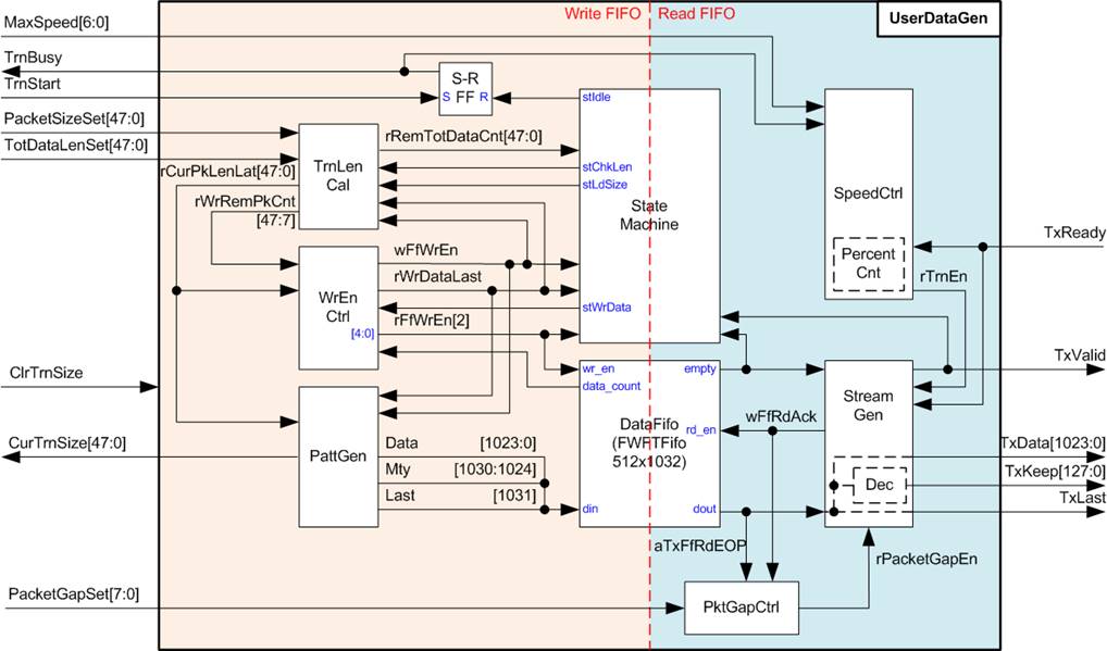
Figure 14 UserDataGen Block Diagram
Figure 14 illustrates the block diagram of UserDataGen. The module includes FWFT FIFO (DataFifo) for buffering the generated test data and packet flags before they are sent over AXI4-ST interface. Internally, the UserDataGen logic is categorized into two main groups based on FIFO function: write-side and read-side logic.
FIFO Write Side
A state machine generates flow control signals for writing each data packet to DataFifo. The write operation concludes when the total written data size reaches the value specified by TotDataLenSet. Three key logic blocks work in coordination with the state machine to implement the write functionality:
1. TrnLenCal (Transfer Length Calculation):
A group of counters responsible for tracking and calculating transfer-related lengths:
· rRemTotDataCnt: Tracks the remaining transfer size in bytes, initialized from TotDataLenSet and decremented after each packet is written to the FIFO.
· rCurPkLenLat: Indicates the current packet size in bytes. This is typically equal to PacketSizeSet, except for the last packet, where the size is taken from rRemTotDataCnt if TotDataLenSet does not align with PacketSizeSet.
· rWrRemPkCnt: A down-counter indicating the number of 1024-bit cycles required to write the current packet. It is calculated from rCurPkLenLat.
2. WrEnCtrl (Write Enable Control):
Manages the assertion of write enables for the FIFO: wFfWrEn and its delayed version, rFfWrEn. It also asserts rWrDataLast for the last transfer cycle. Data is written to the FIFO when the state machine enters the ‘stWrData’ state, and the FIFO data counter indicates sufficient free space.
3. PattGen (Pattern Generator):
Generates 32-bit incremental test data and associated packet flags, including the unused bytes (Mty) and End-of-packet (Last), for writing to the FIFOs. The test data starts at zero and resets to zero whenever a new start flag (TrnStart) or ClrTrnSize is asserted. This block also manages CurTrnSize for progress monitoring.
FIFO Read Side
The FIFO read logic comprises three main components: SpeedCtrl, StreamGen, and PktGapCtrl.
1. SpeedCtrl:
Controls the transmission pacing by introducing pause cycles based on the MaxSpeed setting. A counter manages the assertion of rTrnEn over a 100-cycle window.
i) rTrnEn is asserted to 1b for MaxSpeed cycles.
ii) It is then de-asserted to 0b for the remaining (100 – MaxSpeed) cycles.
iii) If MaxSpeed is set to 100, rTrnEn remains continuously asserted to 1b.
2. StreamGen:
Handles reading data from the FIFO when rTrnEn is asserted to 1b. It considers the readiness of the read data (FIFO is not empty) and the AXI4-ST interface (TxReady) to determine when to read and transmit data. Finally, the output is then formatted and sent over the AXI4-ST interface of UserDataGen.
3. PktGapCtrl:
If PacketGapSet is not zero and the last data of the current packet has been transmitted, rPacketGapEn is asserted to pause the transmission of the first data of the next packet. During the packet-gap period, rPackGapCnt is loaded with PacketGapSet and decremented once per clock cycle until it reaches zero. Following this, transmission of the next packet begins.
Further operation details and timing behavior of UserDataGen are illustrated in Figure 15 and Figure 16.
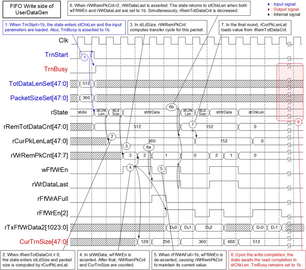
Figure 15 FIFO Write Side of UserDataGen Timing Diagram
1) The operation commences when the user asserts TrnStart to 1b. The state machine enters the stChkLen state, and TrnBusy is asserted to 1b. At this point, the values of TotDataLenSet and PacketSizeSet are loaded to initialize counters in the TrnLenCal logic, including rRemTotDataCnt.
2) In stChkLen, the value of rRemTotDataCnt is checked to determine the next state. If rRemTotDataCnt is non-zero, the state machine proceeds to stLdSize to prepare for packet writing. During this transition, rCurPkLenLat is configured by the current packet size, which is typically equal to PacketSizeSet, except for the last packet.
3) The stLdSize state lasts for one clock cycle and is used to read rCurPkLenLat to compute rWrRemPkCnt, a down-counter representing the remaining number of cycles required to write the current packet to FIFO. Afterward, the state transitions to stWrData.
4) In stWrData, the system writes packet data and flags to FIFOs. The WrEnCtrl logic asserts wFfWrEn to enable FIFO writes if the FIFOs have sufficient space (rFfWrAFull=0b). When wFfWrEn is asserted, rWrRemPkCnt is decremented, and the synchronized write enable (rFfWrEn[2]) is asserted after three clock cycles. Additionally, CurTrnSize is incremented to track the total amount of transferred data.
5) If the FIFOs do not have sufficient free space, rFfWrAFull is set to 1b, immediately de-asserting wFfWrEn. Consequently, rFfWrEn[2] is also de-asserted three cycles later.
6) When rWrRemPkCnt=2 and wFfWrEn=1b, rWrDataLast is set to 1b, indicating that the next data is the last data of the current packet. After wFfWrEn is asserted for writing the last data, rRemTotDataCnt is decremented by the packet size (rCurPkLenLat), and the state returns to stChkLen to check whether more packets need to be written.
7) If the state enters stChkLen to process the last packet, rCurPkLenLat loads the remaining byte count directly from rRemTotDataCnt, which may be less than the user-defined PacketSizeSet.
8) Once the state returns to stChkLen and rRemTotDataCnt=0, the write operation is nearly complete. The last packet will be written to the FIFOs over the next few cycles (to account for D Flip-flops latency). At this point, the state remains in stChkLen until both write and read operations are fully completed. The TrnBusy flag remains asserted to 1b throughout this period.
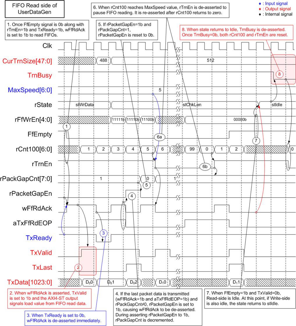
Figure 16 FIFO Read Side of UserDataGen Timing Diagram
1) The read FIFO operation is initiated when three conditions are met: FIFO contains data (FfEmpty=0b), the transfer speed is within the configured limit (rTrnEn=1b), and the TOE200GADV-IP is ready to receive data (TxReady=1b). When all three conditions are met, wFfRdAck is asserted to read data out from the FIFOs.
2) Once wFfRdAck is asserted to 1b, FIFO read data is loaded and becomes the output of the AXI4-ST interface, with TxValid asserted in the following clock cycle.
3) During data transmission, if TxReady is de-asserted to 0b, wFfRdAck is immediately de-asserted to pause FIFO reading.
4) If the current data read from the FIFO is the last packet data, indicated by aTxfRdEOP=1b during the assertion of wFfRdAck, the value of rPackGapCnt is checked. If it is non-zero, rPacketGapEn is asserted to 1b to pause packet transmission by de-asserting wFfRdAck to 0b.
5) While rPacketGapEn is asserted to 1b, rPackGapCnt is decremented on each clock cycle. When rPacketGapEn=1b and rPackGapCnt=1, it indicates the final pause cycle. In the following clock cycle, rPacketGapEn is de-asserted, and wFfRdAck may be re-asserted to resume the transmission of the next packet.
6) Additionally, wFfRdAck can be de-asserted by the SpeedCtrl logic, which includes a 100-cycle counter (rCnt100) used to regulate data flow. When rCnt100 reaches the value set by MaxSpeed, rTrnEn is set to 0b, temporarily pausing FIFO reading. The read operation resumes when rCnt100 resets to zero, re-asserting rTrnEn.
7) When there is no remaining data in the FIFO (FfEmpty=1b) and no packet transfer on the AXI4-ST I/F (TxValid=0b), the read operation is considered complete. If the write operation has also completed, indicated by rFfWrEn[5:0]=0, the state machine returns to the stIdle state.
8) In stIdle, TrnBusy is de-asserted to 0b to indicate that the operation is complete. rTrnEn and rCnt100 are also reset as a result of the TrnBusy de-assertion. Although UserDataGen has finished the transfer, CurTrnSize maintains its value for user monitoring until either a new start (TrnStart) or clear (ClrTrnSize) signal is set.
User Data Verification
Similar to UserDataGen, the UserDataVer submodule within UserReg is designed to facilitate high-speed data reception from the TOE200GADV-IP. In this reference design, four UserDataVer modules are allocated to receive data from four TCP sessions managed by two TOE200GADV-IP instances.
When the user sets the enable flag (RecvEn) to 1b, the module asserts the ready signal to accept the incoming data stream via the AXI4-ST interface and proceeds to verify it. If RecvEn is not asserted, the ready signal is de-asserted, causing data transmission from the TOE200GADV-IP to pause.
As shown in Figure 17, UserDataVer performs three main operations: controlling transfer speed (Block no.1), counting the amount of received data (Block no.2), and verifying the received data (Block no.3). Most of these logics initialize their values on the rising edge of the RecvEn signal, which triggers the start of their respective operations. Further details of each operation are described below.
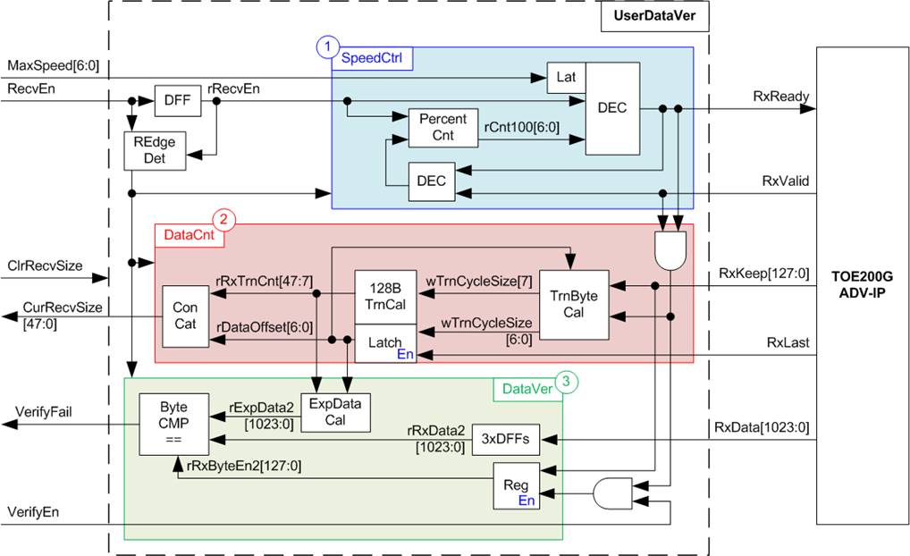
Figure 17 UserDataVer Block Diagram
1. Speed Control:
The logic operates similarly to the corresponding block in UserDataGen. An up-counter (rCnt100) increments from 0 to 99, forming a repeating 100-clock-cycle transfer window. At the beginning of each 100-clock-cycle window, RxReady is asserted to 1b and remains asserted while rCnt100 is below the MaxSpeed limit. It is de-asserted for the remaining cycles and re-asserted when rCnt100 wraps to zero. The MaxSpeed value is loaded upon the new assertion of RecvEn.
2. Data Counter:
This logic tracks and reports the amount of data received from TOE200GADV-IP. Typically, 128 bytes are received per transfer cycle. The last cycle may contain 1-128 bytes of data. The Data Counter comprises two main calculation units.
· TrnByteCal computes the number of valid bytes in each received data. Bit[7] of this signal is asserted when the full 128-byte unit is received. Bits[6:0] represent the data offset (rDataOffSet) for partial data in the last cycle, which is carried over to the next packet.
· 128BTrnCal increments when wTrnCycleSize[7] is asserted, representing the count of fully received 128-byte units. This count is shown by the rRxTrnCnt signal.
The total amount of received data is indicated by a combination of rRxTrnCnt (in 128-byte units) and rDataOffset (remaining bytes). Both counters can be reset by either asserting the clear flag (ClrRecvSize) to 1b or a new rising edge on RecvEn.
3. Data Verification:
The verification logic includes the ExpDataCal block, which calculates the expected data value based on the received data counter from Block no.2. The expected data (ExpData2) is a 1024-bit expected-data bus composed of consecutive 32-bit incremental test-pattern values. When both RecvEn (receive enable flag) and VerifyEn (verification enable flag) are asserted to 1b, each byte of ExpData2 is compared with the received data stream (rRxData2). If a mismatch is detected, the verification failure flag (VerifyFail) is set to 1b to indicate an error. This flag remains set to 1b until either a new RecvEn signal is detected or ClrRecvSize is set to 1b.
3 CPU Firmware (FPGA)
The reference design uses a bare-metal CPU firmware, providing direct control over hardware operations. Further details of the firmware are described in this section.
3.1 Test Firmware (toexgadvtest.c)
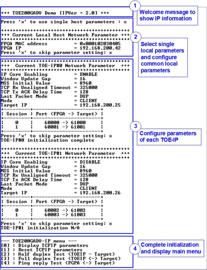
Figure 18 Initialization Sequence of the Demo
Figure 18 illustrates the four-step process for hardware initialization, detailed below.
1) Upon FPGA boot-up, the CPU initializes key peripherals such as UART and timer. A welcome message is then displayed on the console via the UART interface. The CPU awaits Ethernet link establishment by polling EMAC_STS_INTREG[0]. Once the Ethernet link is established, a configuration menu is shown on the console for network parameter setup.
2) When the user inputs ‘x’ or ‘X’ to confirm the use of a single host configuration for both TOE200GADV-IP instances, the same common local parameters - FPGA MAC Address and IP Address - are applied to both IPs. The default values for these parameters are displayed, allowing the user to either proceed with the defaults or modify specific parameters before starting the initialization process. The procedure for updating these parameters is outlined in the Reset parameters menu (refer to section 3.1.2).
Note: The CPU firmware included in this demo supports configuring different local parameters (FPGA MAC Address and IP Address) for each TOE200GADV-IP instance. However, this feature is intended for internal use only and is not documented in the public release. If this functionality is required for your system, please contact our sales team for further assistance.
3) The CPU then displays the default configuration values for the first TOE200GADV-IP, such as TOE200GADV-IP enable flag, Window update gap value, and the port numbers of each TCP session. The firmware provides two predefined parameter sets: the Server initialization set (used only in Server mode) and the Client initialization set (used in both Client and Fixed-MAC modes).
In Fixed-MAC mode, an additional parameter, Target MAC address, is displayed. User may proceed with the default values or modify specific parameters before beginning the initialization process.
The users can select from three IP initialization options to obtain the MAC address of the remote target device: Client, Server, or Fixed-MAC mode. The Client and Server modes are valid only when the TOE200GADV-IP and the target device are on the same network domain. If they are on different networks, the Fixed-MAC mode must be used, allowing users to manually assign the MAC address of the target device, typically based on the Ethernet switch configuration connected to the TOE200GADV-IP. Details for each initialization mode are as follows:
· Client mode: TOE200GADV-IP sends an ARP request packet and retrieve the MAC address from the ARP reply packet.
· Server mode: TOE200GADV-IP waits for an ARP request packet, extracts the MAC address upon reception, and responds with an ARP reply packet.
· Fixed-MAC mode: When the remote target is located on a different IP subnet, Fixed-MAC mode must be configured with the appropriate next-hop destination MAC address, typically the MAC address of the gateway/router.
In a test environment where the remote target device is FPGA, users can configure any of the following initialization options: Client<->Server, Client<->Fixed-MAC, or Fixed-MAC<->Fixed-MAC.
The CPU waits for the initialization process for each enabled TOE200GADV-IP to complete, as indicated by TOE_INF_INTREG[0] being set to 1b. Once initialization is complete, the console displays the message “TOE-IP#<index> initialization complete”.
As shown in Figure 18, the default configuration enables only TOE200GADV-IP#0. Therefore, for the displayed IP (TOE200GADV-IP#1), the console displays the message “TOE-IP#1 IP initialization N/A”.
4) After all TOE200GADV-IP instances are initialized, the CPU displays the main menu, which presents five options. Detailed descriptions for each menu option are provided in the subsequent sections.
3.1.1 Display Parameters
This menu is used to present the current configuration parameters for all TOE200GADV-IP instances. The parameters include:
· IP Core Enabling : Enable status of the TOE200GADV-IP
· Window Update Gap : Assigned to TOE_WIN_INTREG
· MSS Initial value : Assigned to TOE_MSS_INTREG
· TCP Rx Unaligned Timeout : Assigned to TOE_TRT_INTREG
· TCP Tx ACK Delay Time : Assigned to TOE_ACT_INTREG
· Last Packet Mode : Assigned to TOE_LMD_INTREG
· Mode : Assigned to TOE_DMM_INTREG
· FPGA MAC address : Assigned to TOE_SML/H_INTREG
· FPGA IP : Assigned to TOE_SIP_INTREG
· Target MAC address (displayed only in Fixed-MAC mode): Assigned to TOE_DMIL/H_INTREG
· Target IP : Assigned to TOE_DIP_INTREG
· FPGA Port : Assigned to TOE_SPN_INTREG
· Target Port : Assigned to TOE_DPN_INTREG
The sequence for displaying parameters is as follows:
1) Read the FPGA MAC Address and IP Address variables from within the firmware.
2) Print each for these values to the console.
3) Read all parameters for the first TOE200GADV-IP from the internal firmware variables.
4) Print out each of these values.
5) Repeat steps (3) – (4) for all remaining TOE200GADV-IP instances until all parameters have been displayed.
Note: Source (or FPGA) parameters refer to the configuration of the local host, while Target parameters refer to the configuration of the remote target device (e.g. a PC or a TOE200GADV-IP instance on another FPGA).
3.1.2 Reset Parameters
This menu allows users to modify parameters for each TOE200GADV-IP, such as the initialization mode, IP address, and source port number. When a parameter is updated and applied to the corresponding TOE200GADV-IP input signal, the CPU asserts a reset signal to TOE200GADV-IP and related user modules. After the parameter updates, the reset is de-asserted, initiating the IP initialization. The sequence for resetting and reconfiguring the IP is outlined below.
1) Display a confirmation message asking whether to use common host parameters for both TOE200GADV-IP instances.
Note: The ability to configure separate host parameters for each TOE200GADV-IP is reserved for internal use and is not documented. Please contact our sales team if this feature is required for your system.
2) Follow steps (1) – (2) of Section 3.1.1. (Display Parameter) to display the current values of the common host parameters.
3) Prompt the user to either proceed with the current parameters or update them.
· Press ‘x’ to skip step (4) and proceed step (5) using the latest parameters.
· Press any other key to modify the parameter values, proceeding to step (4).
4) Receive updated common host parameters from the user through the following steps.
i) Enter the FPGA MAC address, and validate the input. If the input is invalid, the parameter will not be updated.
ii) Enter the FPGA IP address, and validate the input. If the input is invalid, the parameter will not be updated.
5) Display the latest parameter values for the selected TOE200GADV-IP, following the same sequence as steps (3) – (4) of Section 3.1.1. (Display Parameter).
6) Prompt the user to choose whether to enable the current TOE200GADV-IP. If the user disables it, skip to step (12).
7) Receive updated parameters for the selected TOE200GADV-IP.
i) Prompt the user to select an initialization mode. If a new mode is selected, the latest parameter set for that mode is displayed. The user can press ‘x’ to apply those defaults and proceed to step (8), or continue updating individual fields in step (ii).
ii) Prompt the user to input the remaining parameters. Each input is validated individually. Invalid entries will not be updated.
8) Assert a reset to the selected TOE200GADV-IP, UserDataGen, and UserDataVer by setting HW_RST_INTREG[i] to 1b, where ‘i’ is an index of the targeted TOE200GADV-IP instance.
9) Set all parameter values to the TOE200GADV-IP registers such as TOE_SML_INTREG and TOE_DIP_INTREG.
10) De-assert the hardware reset by setting HW_RST_INTREG[i] to 0b, where ‘i’ is an index of the TOE200GADV-IP instance. This action triggers the initialization process for the selected TOE200GADV-IP.
11) Await the IP initialization process to complete, signified by TOE_INF_INTREG[0] being set to 1b.
12) Move to the next TOE200GADV-IP and repeat steps (5) – (11) until all instances have been configured.
13) If no TOE200GADV-IP is enabled, the firmware returns to step (1), because this demo firmware requires at least one TOE200GADV-IP to be enabled before completing initialization.”
3.1.3 Half Duplex Test
This menu facilitates one-way data transfer (half-duplex) of each TCP session. Users can configure each session independently to perform a Send test, a Receive test, or no operation. Following this, users input relevant parameters such as transfer size, maximum speed, and connection mode (active open for Client mode or passive open for Server mode) to initiate the test.
Note: The required parameters differ between the “Send test” and “Receive test”. Any invalid input will automatically cancel the operation.
In a “Send test”, the logic generates and transmits 32-bit incremental data stream to the target device. On the other hand, in a “Receive test”, users can choose to enable or disable data verification. If the target device is a PC which transmits dummy data to showcase optimal performance, disabling the data verification is recommended to prevent a verification error.
The sequence for performing a half-duplex data transfer is outlined below.
1) Display the IP address of the enabled TOE200GADV-IP instance.
2) Display the port number of the current session.
3) Prompt the user to input and validate parameters: transfer mode, transfer size, packet size, packet gap size, data verification mode, maximum transfer speed, and connection mode.
4) Repeat steps (2) – (3) for each session until all have been configured.
5) Repeat steps (1) – (4) for each enabled TOE200GADV-IP. If all sessions are set to ‘no operation’, the overall process is cancelled.
6) Clear Ethernet statistics (e.g., CRC error packets, packets discarded due to buffer overflow) by setting ETHSTAT_RST_VAL[0] to 1b. Also, reset the interrupt and transfer size registers of each session by setting USR0TX_CMD_INTREG[1] and USR0RX_CMD_CLRSIZE[2] to 1b.
7) Configure the UserReg registers based on the transfer mode.
· Send test: Set maximum speed, packet size, packet gap size, and transfer size using the following registers: USR0TX_TRS_INTREG, USR0TX_PKLL/H_INTREG, USR0TX_GAP_INTREG, USR0TX_LENL/H_ INTREG, respectively.
· Receive test: Set the maximum speed and transfer size using USR0RX_TRS_INTREG and USR0RX_ LENL/H_INTREG, respectively.
8) Read the connection mode of the current active session. If it is set to ‘passive mode’, set the session state variable to ST_CONN_WAIT. Configure parameters including FPGA port number (TOE_SPN_INTREG) and TCP Last mode (TOE_LMD_INTREG), and then initiate the passive open request by setting command register (TOE_CMD_INTREG[1:0]) to the specified session. Repeat this step for all sessions requesting passive open.
9) Display the recommended test application parameters on the PC by reading the current system parameters.
10) If any session uses active open, prompt the user with "Press any key to proceed”, indicating that the target device (PC or FPGA) should be ready and listening. Once passive open has been initiated on the target, the user can proceed by entering keys.
11) For each session configured with active open, set the state variable to ST_CONN_WAIT. Configure the parameters: FPGA port number (TOE_SPN_INTREG), Target port number (TOE_DPN_INTREG), and TCP Last mode (TOE_LMD_INTREG), and then send the active open request using the command register (TOE_CMD_ INTREG[1:0]) to the specified session. Repeat this step for all sessions requesting active open.
12) Begin the data transfer process and monitor each session state until all active connections are closed.
Note: Each TCP session is controlled by a state machine with four states: ST_CONN_WAIT (waiting for connection establishment), ST_CONN_ON (connection active), ST_CONN_OFF (connection closed), and ST_CONN_ERR (connection error).
ST_CONN_WAIT: Wait for connection establishment. Once the connection is established, as indicated by TOE_CON_INTREG, the state transitions to ST_CONN_ON, and UserDataGen or UserDataVer is started by writing to its corresponding command register (USR0TX_CMD_INTREG or USR0RX_CMD_ INTREG). If an active open command fails (TOE_INT_INTREG[8]=1b and TOE_CCS0_INTREG[4]=0b), the state transitions to ST_CONN_ERR, and the session is removed from the active-session count.
After each active session is established, display its Target port number, negotiated MSS, and Target window-scaling factor, read from TOE_TCS0L/H_INTREG.
ST_CONN_ON: The connection is active, and data is being transmitted or received.
Send test
i) If an active close command is in progress, monitor the result and update the session state accordingly.
· If the connection is successfully closed, as indicated by TOE_CON_INTREG, transition to ST_CONN_OFF and decrement the active-session count.
· If the close command fails (TOE_INT_INTREG[8]=1b and TOE_CCS0_INTREG[4]=0b), transition to ST_CONN_ERR and decrement the active-session count.
ii) When UserDataGen completes its operation (USR0TX_CMD_INTREG[0]=0b), check the amount of data remaining in the TxTCP buffer using TOE_TTS0_INTREG. When no data remains, issue the active close command by setting TOE_CMD_INTREG[1:0] and set a flag to indicate that the close command is in progress. If the connection is terminated before the close request is issued, transition to ST_CONN_ERR and decrement the active-session count.
iii) While the connection remains active, as indicated by TOE_CON_INTREG, periodically read USR0TX_LENL/H_INTREG to display the transmission progress every second. If the connection becomes inactive before the data transfer is completed, transition to ST_CONN_ERR and decrement the active-session count.
Receive test
i) Monitor the connection status using TOE_CON_INTREG.
· If the connection becomes inactive, transition to ST_CONN_OFF and decrement the active-session count.
· While the connection remains active, periodically read USR0RX_LENL/H_INTREG to display the amount of received data every second.
ii) After disconnection, verify that the expected data transfer has completed by checking the result in USR0RX_CMD_INTREG and comparing the received data size with the expected value. If data verification fails or the received data size does not match the expected value, display an error message.
13) Calculate and display the test performance results on the console.
3.1.4 Full Duplex Test
This menu enables bidirectional data transfer (full-duplex) for each session with the target device, which may be either a PC or an FPGA. Users can independently configure each session to perform a ‘full-duplex test’ or select ‘no operation’. Afterward, users input the relevant parameters, such as the total transfer size and connection mode (active open/close for Client mode or passive open/close for Server mode).
Note: The transfer size entered by the user must match the transfer size configured on the target device. When using the PC-side test application ‘tcp_client_txrx_single’, the FPGA should be configured in Server mode to perform passive open/close operations.
The sequence for conducting a full-duplex test is outlined below.
1) Receive input parameters from the user, following a process similar to the steps (1) – (5) in Section 3.1.3 (Half Duplex Test).
2) Clear all statistic counters, as performed in step (6) in Section 3.1.3 (Half Duplex Test).
3) For each session enabled for full-duplex operation, configure the UserReg registers. Set the maximum speed for both transfer directions, packet size, packet gap size, and transfer size to the following registers: USR0TX/RX_TRS_INTREG, USR0TX_PKLL/H_INTREG, USR0TX_GAP_INTREG, USR0TX/RX_LENL/H_ INTREG, respectively.
4) Initiate the connection establishment based on the selected connection mode, following the procedure in steps (8) – (11) in Section 3.1.3 (Half Duplex Test).
5) Perform bidirectional data transfer for each active session until all active connections are closed. As in the Half Duplex Test, four state machines are used to manage connection status. While the states are the same, the behavior in each state differs slightly for full-duplex operation, as described below.
ST_CONN_WAIT: The state monitors connection establishment. Once the connection is established, as indicated by TOE_CON_INTREG, the state transitions to ST_CONN_ON, and both UserDataGen and UserDataVer are activated by writing to the command register (USR0TX/RX_CMD_INTREG) for bidirectional operation.
ST_CONN_ON: This state manages bidirectional data transfer. Upon completion of all data transfer, the connection is closed based on the configured mode (active or passive). The termination process varies slightly between the two modes, as follows.
Passive mode
i) Monitor the connection status using TOE_CON_INTREG.
· If it changes to OFF, proceed to the next step.
· Otherwise, periodically display the transmitted and received data sizes from USR0TX/RX_LENL/H_ INTREG every second.
ii) Ensure that the transmission is complete by verifying USR0TX_CMD_INTREG[0]=0b.
· If transmission has completed, set the state to ST_CONN_OFF.
· Otherwise, set the state to ST_CONN_ERR.
When transitioning from ST_CONN_ON to either state, decrement the active-session count.
Active mode
i) If an active close command is in progress, the next state is determined as follows:
· If the connection closes successfully (TOE_CON_INTREG indicates OFF), transition to ST_CONN_OFF and decrement the active-session count.
· If the command fails (TOE_INT_INTREG[8]=1b and TOE_CCS0_INTREG[4]=0b), transition to ST_CONN_ERR and decrement the active-session count.
ii) If the connection terminates before UserDataGen completes, transition to ST_CONN_ERR and decrement the active-session count. Otherwise, proceed to the next step.
iii) Monitor the completion status of UserDataGen (USR0TX_CMD_INTREG[0]).
· If incomplete (return non-zero value), continue displaying the progress of both transmission and reception every second using USR0TX/RX_LENL/H_INTREG (representing the total transmitted and received data counts).
· Once transmission is complete, wait for UserDataVer to finish, indicated by USR0RX_LENL/H_INTREG matching the user-defined transfer size. Once confirmed, send the active close command by setting TOE_CMD_INTREG[1:0] with an assertion flag to indicate the connection close command is in process.
6) After connection termination, read the verification result from USR0RX_CMD_INTREG and compare the total amount of received data with the expected transfer size. If a verification error or mismatch is found, display an error message.
7) Calculate and display the performance statistics on the console.
3.1.5 Ping Reply Test
When a PC executes the Ping command to check network reachability and measure the round-trip time, it sends an ICMP Echo Request packet. This menu configures the UserRxMAC module to receive ICMP Echo Request packets. Upon receiving a valid Echo Request packet, the hardware generates and transmits an ICMP Echo Reply packet via UserTxMAC module.
The packet structure for ICMP Echo Request/Reply message is illustrated in Figure 19.
Note: The ‘Type’ field value is set to 8 for an Echo Request and 0 for an Echo Reply. For more information about the Ping command and ICMP protocol, refer to the following website:
http://en.wikipedia.org/wiki/Ping_(networking_utility)
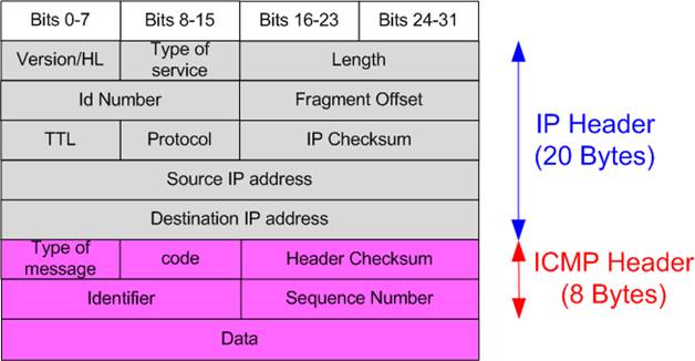
Figure 19 Packet Structure for ICMP Request/Reply Packet
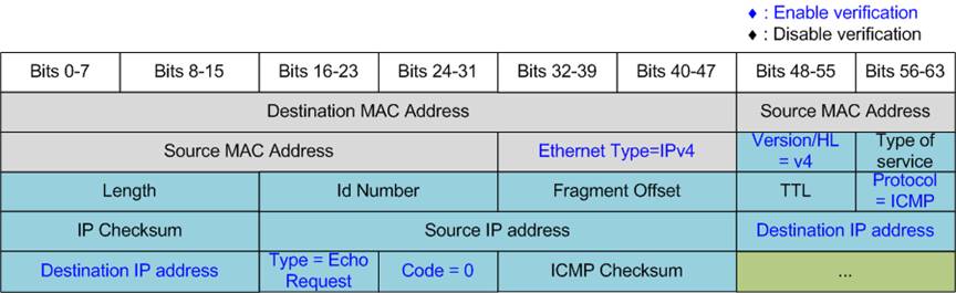
Figure 20 ICMP Echo Request Packet Filtering
The sequence for running the Ping reply is described as follows.
1) Call the ‘init_filter’ function to configure the filtering parameters of the UserRxMAC module, enabling it to receive only ICMP Echo Request packets. The expected configuration values for the ICMP Echo Request are listed below (highlighted in blue in Figure 20).
· Ethernet Type (2 bytes) = 0x0800 (IPv4)
· IP version/HL (1 byte) = 0x45 (IP Version4, 20-byte header)
· Protocol (1 byte) = 0x01 (ICMP Protocol)
· Destination IP Address (4 bytes) = IP address of the local host (FPGA)
· ICMP Type (1 byte) = 0x08 (Echo Request)
· ICMP Code (1 byte) = 0x00 (Echo Request code)
Note: Figure 20 illustrates only the first 38 bytes of the ICMP packet. The minimum header length for the ICMP packet is 42 bytes (14-byte Ethernet + 20-byte IPv4 + 8-byte ICMP header). The UserRxMAC filtering logic supports filtering up to the first 38 bytes of packet data, excluding the rest of the fields.
2) Enable the UserRxMAC module by setting RXEMAC_CMD_INTREG[0] to 1b.
3) Wait until a new packet is stored in RxRAM, as indicated by the empty flag of RxMacFf being cleared (RXEMAC_FF_INTREG[15]=0b).
4) Read and validate the last address of the received packet from RxMacFf (RXEMAC_FF_INTREG[4:0]). After that, assert the read acknowledge signal by setting RXEMAC_CMD_INTREG[1]=1b to flush the current entry from RxMacFf.
5) Copy the received packet from RxRAM (RXRAM_BASE_ADDR) to the temporary receive buffer (rxbuf_ch).
6) Decode and validate the received packet.
· If it is a valid Echo Request and all parameters – including checksums – are correct, proceed to the next step.
· Otherwise, display an error message.
7) Prepare the ICMP Echo Reply packet in the temporary transmit buffer (txbuf_ch), including the calculated IP checksum and ICMP checksum. After that, copy the prepared packet from txbuf_ch to TxRAM (TXRAM_BASE_ADDR).
8) Initiate packet transmission by setting the Echo Reply length in TXMAC_LEN_INTREG, triggering the UserTxMAC module to transmit the packet.
9) Return to step (3) to wait for the next ICMP Echo Request packet. This loop continues indefinitely until the user presses a key on the console. Upon user interruption, ensure that all data is cleared from both RxMacFf and RxRAM, and disable the UserRxMAC module by setting RXEMAC_CMD_INTREG[0]=0b. This halts the low-speed port processing and returns to the main menu.
3.2 Function List in Test Firmware
This section outlines the list of functions available in the test firmware, categorized into two groups: functions for high-speed connection and functions for low-speed connection. Further details for each function are provided below.
3.2.1 Function for High-Speed Connection
|
unsigned int cal_strlen(unsigned int num) |
|
|
Parameters |
num: Integer input for which the string length is to be calculated. |
|
Return value |
Returns the length of the string required to display the integer value. |
|
Description |
Calculate and return the number of characters needed to represent the input integer as a string. |
|
void check_cmd_cpl(unsigned int ipcore, unsigned int session, unsigned int* status) |
|
|
Parameters |
ipcore: The index of the TOE200GADV-IP instance. session: The session number. status: Pointer to a variable that will store the command completion status. 0: Processing, 1: Failure, 2: Success |
|
Return value |
None |
|
Description |
Read the TOE_INT_INTREG register to monitor command completion for the specified session, defined by the ‘session’ parameter. If a completion flag is detected, the function clears the flag by writing to TOE_INT_INTREG and sets the completion status (success or failure) in the ‘status’ parameter. |
|
void check_connon(unsigned int ipcore, unsigned int session, unsigned int* status) |
|
|
Parameters |
ipcore: The index of the TOE200GADV-IP instance. session: The session number. status: Pointer to a variable that will store the connection status. 0: Connection OFF, 1: Connection ON. |
|
Return value |
None. |
|
Description |
Read the TOE_CON_INTREG register for the specified session, defined by the ‘session’ parameter, and store the connection status in the ‘status’ parameter. |
|
void check_ethlink(unsigned int* status) |
|
|
Parameters |
status: Pointer to a variable that will store the Ethernet link status. 0: Link down, 1: Link up |
|
Return value |
None |
|
Description |
Read the Ethernet MAC link status from EMAC_STS_INTREG and stores the result in the ‘status’ parameter. |
|
void deactivate_session(unsigned int* wait_conn_off, unsigned int* num_act_session) |
|
|
Parameters |
wait_conn_off: Pointer to a flag indicating that an active close is in progress. num_act_session: Pointer to a variable holding the current number of active sessions. |
|
Return value |
None. |
|
Description |
Reset the ‘wait_conn_off’ parameter to indicate the completion of the connection close request and decrement the number of active sessions (num_act_session). This function is used for session cleanup after the connection is terminated. |
|
void init_conn(TEST_PARAM* testparam, unsigned int* num_act_session, unsigned int* num_aop_session, unsigned int* cur_state). |
|
|
Parameters |
testparam: Pointer to a structure containing user-defined test parameters such as operation mode, connection mode, and maximum speed. num_act_session: Pointer to the variable storing the number of active sessions. num_aop_session: Pointer to the variable storing the number of sessions configured for active open. cur_state: Pointer to the variable representing the current connection state. |
|
Return value |
None. |
|
Description |
Initialize UserDataGen, UserDataVer, and the connection establishment before starting data transfer in both Half Duplex Test and the Full Duplex Test. |
|
void init_param(void) |
|
|
Parameters |
None |
|
Return value |
None |
|
Description |
Execute the ‘Reset parameters’ menu as described in Section 3.1.2. It internally calls ‘show_param’, ‘show_local_param’, ‘input_local_param’ and ‘input_param’ functions to display and retrieve user parameters. |
|
void input_local_param(void) |
|
|
Parameters |
None |
|
Return value |
None |
|
Description |
Prompt the user to input the FPGA MAC Address and FPGA IP Address. Each input is validated separately. Valid entries are updated while invalid inputs are ignored. |
|
void input_param(unsigned int ipcore) |
|
|
Parameters |
ipcore: The index of the TOE200GADV-IP instance. |
|
Return value |
None |
|
Description |
Receive network parameters from the user, including TOE200GADV-IP enable flag, Initialization mode, Last packet mode, Window update threshold, MSS initial value, Rx unaligned timeout, Tx ACK delay time, FPGA port number, Target IP address, Target port number, and Target MAC address (required only in Fixed-MAC mode). Each input is validated individually. If a parameter is valid, it will be updated; otherwise, it will remain unchanged. After receiving all parameters, the function calls the ‘show_param’ to display the configured values. |
|
int input_test_param(unsigned int test_menu, TEST_PARAM* testparam, unsigned int* num_act_session, unsigned int* num_aop_session) |
|
|
Parameters |
test_menu: The selected test menu (either half-duplex or full-duplex). testparam: Pointer to a structure containing user-defined test parameters such as operation mode, connection mode, and maximum speed. num_act_session: Pointer to the variable storing the number of active sessions. num_aop_session: Pointer to the variable storing the number of sessions using active open mode. |
|
Return value |
0: Valid input, -1: Invalid input |
|
Description |
Receive test parameters for all enabled TOE-IP cores and sessions, including Operation mode, Transfer size, Packet size, Packet gap size, Data verification mode, Maximum speed, and Connection mode. If any input is invalid, the operation is cancelled. After validation, the number of active sessions and the number of sessions configured for active open mode are calculated and returned via ‘num_act_session’ and ‘num_aop_session’. |
|
void show_cursize(TEST_PARAM* testparam, unsigned int* cur_state, unsigned long long* cur_txsize, unsigned long long* cur_rxsize) |
|
|
Parameters |
testparam: Pointer to a structure containing user-defined test parameters such as operation mode, connection mode, and maximum speed. cur_state: Pointer to the variable representing the current connection state. cur_txsize: Pointer to the variable storing the current transmitted data size in bytes. cur_rxsize: Pointer to the variable storing the current received data size in bytes. |
|
Return value |
None |
|
Description |
Update and display the connection status of all sessions. If the data is ongoing, read the current amount of transmitted and received data from USRTX/RX_LENL/H_ INTREG, and then display it in Byte, KB, MB, GB, or TB on the console. |
|
void show_eth_status(void) |
|
|
Parameters |
None |
|
Return value |
None |
|
Description |
Read the current Ethernet MAC status from EMAC_STS_INTREG, decode the status bits, and display result on the console. |
|
void show_local_param(void) |
|
|
Parameters |
None |
|
Return value |
None |
|
Description |
Execute the ‘Display parameters’ menu according to steps (1) – (2) of Section 3.1.1, which involve displaying the current local (FPGA) MAC address and IP Address. |
|
void show_param(unsigned int ipcore) |
|
|
Parameters |
ipcore: The index of the TOE200GADV-IP instance. |
|
Return value |
None |
|
Description |
Execute the ‘Display parameters’ for the selected TOE200GADV-IP instance, as described in steps (3) – (4) of Section 3.1.1. |
|
void show_perf_header(unsigned int *test_mode) |
|
|
Parameters |
test_mode: Pointer to the current test mode. 0: No test, 1: Send test, 2: Receive test, 3: Full-duplex. |
|
Return value |
None |
|
Description |
When ‘test_mode’ is not set to ‘No test’, this function displays the header of the current status table, including the TOE-IP core number and session number for active session. |
|
void show_perf_line(unsigned int *test_mode) |
|
|
Parameters |
test_mode: Pointer to the current test mode. 0: No test, 1: Send test, 2: Receive test, 3: Full-duplex. |
|
Return value |
None |
|
Description |
When ‘test_mode’ is not set to ‘No test’, this function displays a horizontal separator line used in the formatting of the current status table. |
|
void show_port_info(TEST_PARAM* testparam, unsigned int* cur_state, unsigned int* disp_1st_stat) |
|
|
Parameters |
testparam: Pointer to a structure containing user-defined test parameters such as operation mode, connection mode, and maximum speed. cur_state: Pointer to the variable representing the current connection state. disp_1st_stat: Flag indicating whether this is the first line of output for connection status display. |
|
Return value |
None |
|
Description |
Scan active sessions using the ‘testparam’ parameter. If the connection status is ON, display its information including the Target port number, negotiated MSS, and the target window-scaling factor (TOE_TCS0L/H_INTREG). This information is displayed once after connection establishment. |
|
void show_reset_int_status(unsigned int ipcore, unsigned int session) |
|
|
Parameters |
ipcore: The index of the TOE200GADV-IP instance. session: The session number. |
|
Return value |
None |
|
Description |
Read and decode the Reset interrupt status for the specified TOE-IP core and session (via TOE_RSS0_INTREG) and displays the cause of the reset. |
|
void show_result(TEST_PARAM* testparam, unsigned int* cur_state, unsigned long long* cur_txsize, unsigned long long* cur_rxsize, unsigned int *recv_size_err, unsigned int *recv_ver_err) |
|
|
Parameters |
testparam: Pointer to a structure containing user-defined test parameters such as operation mode, connection mode, and maximum speed. cur_state: Pointer to the variable representing the current connection state. cur_txsize: Pointer to the variable storing the current transmitted data size in bytes. cur_rxsize: Pointer to the variable storing the current received data size in bytes. recv_size_err: Error flag asserted by receive size mismatch. recv_ver_err: Error flag asserted by received data verification failure. |
|
Return value |
None |
|
Description |
Check for errors including connection error, receive size mismatch, and data verification failure by reading the ‘cur_state’, ‘recv_size_err’, and ‘recv_ver_err’ parameters, respectively. Display the corresponding error message for each condition. After that, read USRTX/RX_LENL/H_INTREG to display the total amount of transmitted and received data. Also, read timer value from the STAT0_TX/RXTIML/H_INTREG registers to calculate and display the total processing time in usec, msec, or sec. Finally, calculate and display the transfer performance in MB/s and the total interrupt count from each TOE200GADV-IP instance. |
|
void show_retry_int_status(void) |
|
|
Parameters |
None |
|
Return value |
None |
|
Description |
Track retry interrupts for each session and decode TOE_RTS*_INTREG. When the same retry condition occurs repeatedly, display the status every fourth occurrence. |
|
void show_space_line(TEST_PARAM* testparam) |
|
|
Parameters |
testparam: Pointer to a structure containing user-defined test parameters for all TOE-IP cores and sessions. This function uses testparam->test_mode to identify the active test sessions. |
|
Return value |
None |
|
Description |
Scans all TOE-IP cores and sessions. For each session whose ‘test mode’ is not set to ‘No test’, the function displays an empty cell to form an empty row in the current status table. |
|
int toe_full_test(void) |
|
|
Parameters |
None |
|
Return value |
0: The operation is successful. -1: Receive invalid input or error is found. |
|
Description |
Execute the ‘Full duplex test’ menu, following the procedure described in Section 3.1.4. |
|
int toe_half_test(void) |
|
|
Parameters |
None |
|
Return value |
0: The operation is successful. -1: Receive invalid input or error is found. |
|
Description |
Execute the ‘Half duplex test’ menu, following the procedure in Section 3.1.3. |
|
void update_cursize(unsigned long long* cur_txsize, unsigned long long* cur_rxsize) |
|
|
Parameters |
cur_txsize: Pointer to the variable storing the current transmitted data size in bytes. cur_rxsize: Pointer to the variable storing the current received data size in bytes. |
|
Return value |
None |
|
Description |
Read the current Tx and Rx transfer-size registers (USRTX_LENL/H_INTREG and USRRX_LENL/H_INTREG registers) for all TOE-IP cores and sessions. Combines the read value into 48-bit transfer size value and stores the results in ‘cur_txsize’ and ‘cur_rxsize’. |
|
void update_curstat(unsigned int* disp_1st_stat, TEST_PARAM* testparam, unsigned int* cur_state, unsigned long long* cur_txsize, unsigned long long* cur_rxsize, unsigned long long* prv_txsize, unsigned long long* prv_rxsize) |
|
|
Parameters |
disp_1st_stat: Flag indicating whether this is the first line of output for connection status display. testparam: Pointer to a structure containing user-defined test parameters such as operation mode, connection mode, and maximum speed. cur_state: Pointer to the variable representing the current connection state. cur_txsize: Pointer to the variable storing the current transmitted data size in bytes. cur_rxsize: Pointer to the variable storing the current received data size in bytes. prv_txsize: Pointer to the latest value of ‘cur_txsize’ before updating. prv_rxsize: Pointer to the latest value of ‘cur_rxsize’ before updating. |
|
Return value |
None |
|
Description |
Check the current state machine and both transmit/receive sizes, and then displays all information in table format by calling ‘show_port_info’ and ‘show_cursize’ functions. If additional data has been transferred, the interrupt count is cleared. If an interrupt is detected, the function calls ‘show_retry_int_status’ to decode and display the interrupt status. |
|
void ver_recv_data (TEST_PARAM* testparam, unsigned int* cur_state, unsigned int *recv_size_err, unsigned int *recv_ver_err) |
|
|
Parameters |
testparam: Pointer to a structure containing user-defined test parameters such as operation mode, connection mode, and maximum speed. cur_state: Pointer to the variable representing the current connection state. recv_size_err: Error flag asserted by receive size mismatch. recv_ver_err: Error flag asserted by received data verification failure. |
|
Return value |
None |
|
Description |
Wait until all sessions operating in Receive Test or Full Duplex Test modes have received and forwarded all data to UserDataVer (verified by TOE_TRS0_INTREG=0). After that, read USR0RX_CMD_INTREG[0] to update the verification error status to ‘recv_ver_err’. It also reads USRRX_LENL/H_INTREG to check and update the receive size status to ‘recv_size_err’. |
|
void wait_ethlink(void) |
|
|
Parameters |
None |
|
Return value |
None |
|
Description |
Read EMAC_STS_INTREG[0] to monitor the Ethernet link status. The function completes when the Ethernet connection is successfully established. |
3.2.2 Function for Low-Speed Connection
|
unsigned int cal_checksum (unsigned int byte_len, unsigned char *buf) |
|
|
Parameters |
byte_len: The data length in bytes buf: Pointer to the first byte data position |
|
Return value |
The calculated 16-bit checksum of the data |
|
Description |
Calculate a 16-bit checksum of the given data. The user must provide a character-type data array and specify its length in bytes. The function returns the computed checksum value based on the contents of the array. |
|
void init_filter (unsigned int ipcore) |
|
|
Parameters |
ipcore: The index of the TOE200GADV-IP instance. |
|
Return value |
None |
|
Description |
Disable the UserRxMAC module by setting RXEMAC_CMD_INTREG to block the incoming packets. Next, write filtering values to RXEMAC_HDVAL_ADDR and RXEMAC_HDEN_ADDR to configure the module to receive only ICMP Echo Request packets, as shown in the blue text in Figure 20. |
|
void ping_test (void) |
|
|
Parameters |
None |
|
Return value |
None |
|
Description |
Execute the ‘Ping reply test’ menu as described in Section 3.1.5, enabling the system to receive ICMP Echo Requests and send back Echo Replies. |
|
unsigned int prepare_rxbuffer (void) |
|
|
Parameters |
None |
|
Return value |
Number of 32-bit words copied from RxRAM. Returns 0 when no packet is available |
|
Description |
Check RXEMAC_FF_INTREG to determine if a packet has been received via the low-speed connection. If a packet is present, read its length from RXEMAC_FF_INTREG, remove the read data from RxMacFf by setting RXEMAC_CMD_INTREG[1]=1b, and copy the data from RxRAM inside UserRxMAC (RXRAM_BASE_ADDR) to a local character buffer. Finally, return the length of the received packet in 32-bit unit. |
4 Test Software (PC)
4.1 “tcpdatatest” Application (Half Duplex Test)
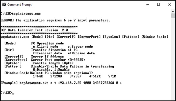
Figure 21 “tcpdatatest” Application
The ‘tcpdatatest’ application is used to transmit or receive TCP payload data on a PC. It requires six mandatory parameters and one optional parameter. Ensure that the parameter inputs match those configured on the FPGA. The details for each parameter are outlined below.
Mandatory Parameters
1) Mode : c – The PC runs in Client mode while the TOE200GADV-IP on the FPGA runs in Server mode.
s – The PC runs in Server mode while the TOE200GADV-IP on the FPGA runs in Client mode.
2) Dir : t – transmit mode (the PC sends data to the FPGA)
r – receive mode (the PC receives data from the FPGA)
3) ServerIP : The local host IP address of the TOE200GADV-IP on FPGA when the PC runs in Client mode
(Default is 192.168.200.42)
4) ServerPort : The local port number of the TOE200GADV-IP on FPGA when the PC runs in Client mode
(Default is 60000)
5) ByteLen : The total size of data to be transferred in bytes. This parameter is used only in Transmit mode
and is ignored in Receive mode. In Transmit mode, the ‘ByteLen’ value must match the total
transfer size set in the ‘Receive Data Test’ menu on the FPGA. In Receive mode, the application
terminates once the connection is closed.
6) Pattern : 0 – Generate dummy data in Transmit mode and disable data verification in Receive mode.
1 – Generate incremental data in Transmit mode and enable data verification in Receive mode.
Optional Parameter
Window scaling feature. The valid range is 1-5.
1 – Allocated buffer size of 64 KB
2 – Allocated buffer size of 128 KB
3 – Allocated buffer size of 256 KB
4 – Allocated buffer size of 512 KB
5 – Allocated buffer size of 1 MB
Note: The Window Scale parameter is an optional setting. If the user does not provide this parameter, it is automatically set to 1.
The sequence of the test application when running in Transmit mode and Receive mode are detailed below.
Transmit Mode
1) Obtain and validate the user’s input parameters, excluding the optional Window Scale parameter.
2) Create a TCP socket, configure the socket options, and specify the socket memory size.
3) Establish a new TCP connection using the provided Server IP address and Server port number.
4) Allocate 2 MB of memory for the send buffer.
5) If the dummy pattern is not selected, generate an incremental test pattern to the send buffer.
6) Send data through the socket and keep track of the total amount of data sent.
7) Calculate the remaining data size to be transmitted.
8) Display the total amount of data transmitted every second.
9) Repeat steps (5) – (8) until all the data has been transferred (the remaining transfer size reaches 0).
10) Calculate the overall transfer performance and display the result on the console.
11) Close the socket and free the allocated memory.
Receive Mode
1) Follow steps (1) – (3) of the Transmit Mode sequence.
2) Allocate 2 MB of memory for the receive buffer.
3) Receive data from the socket into the receive buffer and update the total amount of received data.
4) If data verification is enabled, compare the received data with the incremental pattern. Print an error message if a mismatch is detected. If verification is disabled, skip this step.
5) Display the total amount of received data every second.
6) Repeat steps (3) – (5) until the connection is closed by the transmitting device.
7) Calculate the overall transfer performance and display the result on the console.
8) Close the socket and free the allocated memory.
4.2 “tcp_client_txrx_single” Application (Full Duplex Test)
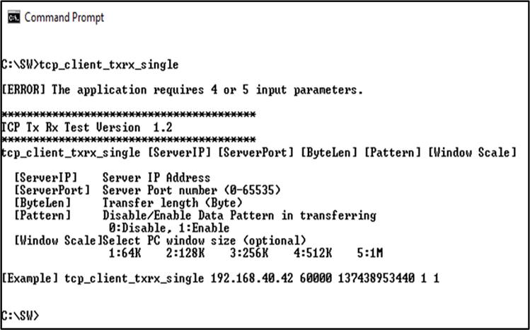
Figure 22 “tcp_client_txrx_single” Application
The “tcp_client_txrx_single” application allows the PC to simultaneously transmit and receive TCP payload data over Ethernet using the same port number. This application runs exclusively in Client mode and requires Server parameters (the local network parameters for TOE200GADV-IP) to be input by the user. The application uses five parameters, outlined below.
Mandatory parameters
1) ServerIP : The local IP address of the TOE200GADV-IP on the FPGA.
2) ServerPort : The local port number of the TOE200GADV-IP on the FPGA.
3) ByteLen : The total transfer size in bytes, representing the total amount of transmitted and received data.
This value must match the transfer size set on the FPGA for the full duplex test.
4) Pattern : 0 – Use dummy data for transmission and disable data verification for the receiving function.
This mode is used to measure the maximum performance of full-duplex transfer.
1 – Generate incremental data for transmission and enable data verification for the
receiving function.
Optional parameter
1) Window Scale : Indicate the size of the allocated buffer for the TCP socket on the PC and control the TCP
Window scaling feature. The valid range is 1-5.
1 – Allocated buffer size of 64 KB
2 – Allocated buffer size of 128 KB
3 – Allocated buffer size of 256 KB
4 – Allocated buffer size of 512 KB
5 – Allocated buffer size of 1 MB
Note: The Window Scale parameter is an optional setting. If the user does not provide this parameter, it is automatically set to 1.
The sequence of the test application when running the application is detailed below.
1) Obtain and validate the user’s input parameters, excluding the optional Window Scale parameter.
2) Allocate 2 MB of memory separately for the send and receive buffers.
3) Create a TCP socket, configure the socket options, and specify the socket memory size.
4) Establish a new TCP connection using the provided Server IP address and Server port number.
5) Repeatedly process Tx and Rx operations while the connection is active until both transfer directions are complete.
Transmit Operation
i) If transmitted data remains, prepare the next block of data. If incremental test pattern is selected, generate the corresponding incremental pattern. Otherwise, use dummy data.
ii) Send the data through the socket and keep track of the total amount of data sent.
iii) Calculate the remaining data size to be transmitted.
Receive Operation
i) If the socket has received data available, receive the data into the receive buffer and update the total amount of received data.
ii) If the test pattern is enabled, verify the received data against the expected incremental pattern, and print an error message if verification fails; otherwise, skip this step.
6) Display the total amount of transmitted and received data every second.
7) Repeat steps (5) – (6) until both the total transmitted data and the total received data each equal ‘ByteLen’ value set by the user.
8) Calculate the transmit and receive performance and print the results on the console.
9) Close the socket and free the allocated send and receive buffers.
5 Revision History
|
Revision |
Date (D-M-Y) |
Description |
|
1.00 |
27-Aug-26 |
Initial version release |